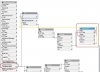
Premise can send UPB links via a Serial UPB PIM. The easiest way to do so is to navigate to the upbSerialInterface device in explorer and type in a command into the "link data" field and hit return. This will immediately transmit the link and if you're lucky the linked devices will respond.
The link data is in this basic format of {nid}{link}{mdid}{data} where
Nid = hex network id;
Link = hex device id;
Mdid = hex command;
Data = optional hex data.
Since "data" is optional I don't use it since I have no idea what it does. :unsure:
What I struggled with is what do all those 3 and 4 letter format definitions translate to. In short, here's an example - C80C21. A total of 6 characters is all that is needed. Here is my newbie translation:
NID (the "C8" in the example)- Pull up any of your UPB devices in Premise explorer and you will find the Network ID number within the object properties. Suppose your ID is 200. Find a decimal to hex converter such as http://www.easycalculation.com/decimal-converter.php and enter in your Network ID and out pops the Hex equivalent of C8. Again, you code heads might have this memorized but for me I sought google for help.
Link (the "0C" in the example)- This is the link you want to transmit. In UpStart, hit Links then Link Names and there are your listed links along with the Link ID which is what you need. Suppose your link ID is 12. Go to your converter and you should get "C". Remember you need two characters for this field so just enter a zero before the C.
Mdid - This basically is the command to transmit the link. Simply use 20 to activate the link and 21 to deactivate the link.
Therefore, in my example - the string will activate link 12 on my network that has a network id of 200.
Lastly, you can include in a script. I have yet to do so but suspect you can can embed the script into a scene or object or bind to a button. Here is a property change script that works. This is a script that runs on a property change.
If sysevent.newVal Then
Devices.upb.upbSerialInterface.upbLinkData = "C80921"
End If
Now, anybody know how to receive a link and parse the data???
Thanks to Sam and George for their help to get me up and running with UPB.
-acb