Terminal boards for WebControl

rossw

Active Member
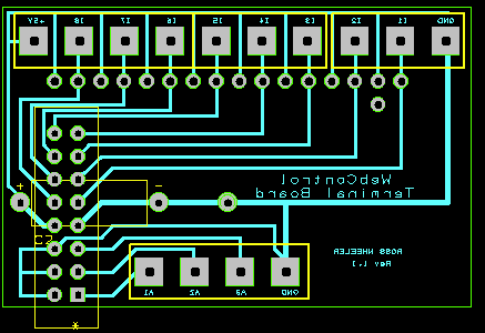
I saw comments in here before about terminal breakout boards for the webcontrol, and that none were really suitable - needed bits cut or nicked out etc.

Did anyone fine anything suitable in the end? If not, I've layed out a board that I plan to have a bunch made, and will be happy to supply them to people who want - either as a bare board, or with the components already populated.

I've designed it to fit over the top of the existing webcontrol board. One row of terminals for digital inputs (with a ground), a second row for analog inputs (also with ground). Accessable tracks so you can isolate the analog ground from digital, if you wish.

I also put a cap on the board that might assist with reducing the analog input noise/jitter.

The extra pad by the digital input terminals, between I1 and Gnd is for an optional standoff that can rest on the webcontrol board just beside the processor, so the header doesn't need to take all the weight.

If anyone wants to pre-order, please let me know. Otherwise there will be "some" available, but once gone that'll probably be it.
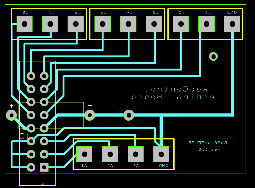
webcontrolterminals.gif


I plan to make an additional board shortly that will have some signal conditioning (including amplifiers for the A/D) if anyone has any particular interest in that?
 
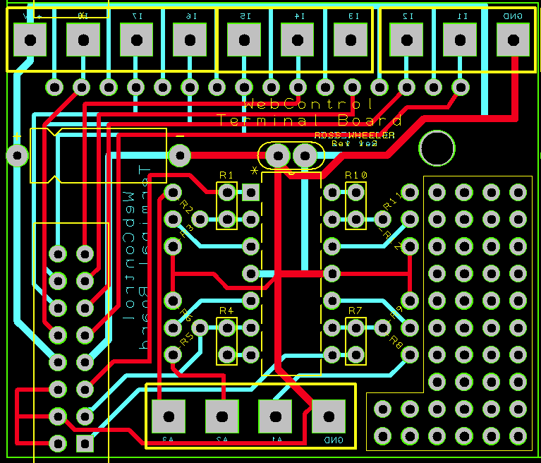
Didn't last long.... Rev 1.1 proposed already. I've made the board slightly longer (now 2" x 1.3") and added an extra connector to bring out the +5V (handy if you want to pull switches high, or power low-power sensors), and also added room for 8 pullup (or with a small cut to the board, they can be pulldown) resistors to the TTL inputs.

webcontrolterminals1-1.gif
 
That looks great. Any idea what you will need for the populated board? date of availability?

I haven't got a firm quote on manufacture yet, until I've got some idea on quantities.
Availability is probably several weeks because I won't order them until I've got a ballpark quantity... if I get say, 5 made for me I'm going to look silly if 50 people here want them. And you can bet if I get 50 made, nobody else will want them.... (and price changes with quantity!)
 
Nice looking board! Is that possible to also have the operational amplifier traces laid on the baord? If anyone needed, he could buy a chip and solder it on.
 
Nice looking board! Is that possible to also have the operational amplifier traces laid on the baord? If anyone needed, he could buy a chip and solder it on.

Peoples applications will vary. For example, my immediate application is for 3 channels that will have a gain of about -140.
Yes, -140. I have an input that goes between 0 and 35mV below ground. It may be possible to leave enough pads to use resistors and jumpers to set up for different application. I'll think about it....
 
check batch pcb.

they make batches by putting a bunch of peoples pcbs together.

I'll take 2 .
 
OK, hasn't even gotten off the drawing board yet and I'm up to Rev 1.2

I've added opamp, with careful placement of parts you can put a resistor in either of two places to use that channel as an inverting or non-inverting amplifier.

I've also put some blank pads in an area for people who might want something small but different.

Anything else on the "wish list" before I send these off for fabrication?

webcontrolterminals-v1.2.gif
 
It looks nice. If making large qty, the cost will be very reasonable.
One question, if you make the board little taller, would you be able to have a header to hold to the 5 pin header J3? Even you don't get any signal from that, the board might rest better. On that header, pin 3 is ground, pin 5 is 3.3VDC.
 
is it too late?

what about changing the silk screen (or is that copper) labels for the digital inputs to what input they are, why not make the board a little longer so you can see the names in front of the terminal block?
 
OK, I'll have to stop fiddling soon or they'll never get made!
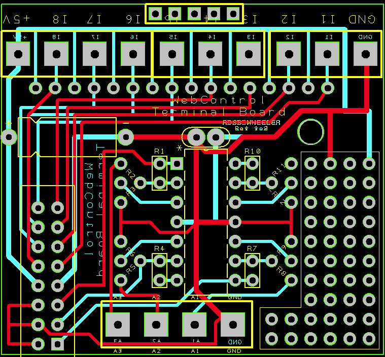
Extended the board enough to pick up J3 by installing an optional female SIL header.
Added text to silkscreen layer for input terminal labels.
Not so obvious, added +V and Ground to two pins on the prototyping area. They are 0.2" apart, so a 2-pin terminal can be added.
Why? Some of us may choose to power the board from 12V so we can get the full 0-10V swing out of the opamps. This will entail cutting the +5V track that leads to the opamp to isolate it, then supplying power via the proto area. (This could possibly be a small SMPS to generate the 10V on-board). It also provides a convenient place to get power/ground for anything you do choose to make on the proto area. (Thinking here of zeners, voltage dividers etc)

Any more "last minute" requests?
webcontrolterminals-v1.2a.gif
 
If you can incorporate this DC-DC converter to the board, then user can use any input voltage
http://www.ebay.com/itm/251066005460
this is more energy efficient than the regulator chip, can work on HVAC power(it has diode), too.

Yeah, something like that was on my mind - I've used dozens of them, but that is FAR too big to incorporate on my board.
That is 48x23mm. My board is (now, after adding extra length for the J3 connector and text for connectors) 49 x 46mm, so adding that to my board would add 50% to the area!

http://tinyurl.com/d6f4dhp is smaller, only 30x19mm, but still quite large.
Tempted to get some of http://tinyurl.com/bqa7wta and see if they're small enough with the USB connector stripped off :)
 
Back
Top