I've come up with Two possible ways to wire this and both methods utilize a DPDT relay being we purchased the B2 wired boards. The DPDT Relay I have chosen is the ELK-924 Sensitive Relay for around 15 dollars. Two different powers are required (Trigger & Supply).
Trigger ->> Requirements for this ELK-924 are very low at only 1.2 milliamp and most any alarm output can handle this. The trigger is used to change the polarity of the water valve. When Voltage is applied to the trigger input the water valve will open (but the supply voltage must also be present).
Supply -->> Requirements for each Water Valve are (KLD20S is 3 watts or 250 milliamps; KLD100 is 15 watt or 1500 milliamps).. Also the Coil on the DPDT has a current draw of 60 milliamps. When you combine the load of the motorized valve and coil relay you will far exceed the potential of a regular alarm panel output, thus if you desire to have switched supply power you will have to run a SPDT relay prior to the ELK-924 Relay.
Personally I plan to wire mine in using method 1 because in the event of electrical loss or trigger not being applied the water valve will be in the closed position. Just my preference but time will tell.
1) Failsafe method to close the valve when Trigger voltage is not applied to the relay. To achieve this, Fused DC voltage must be constantly applied to the POS & NEG Supply so that the relay will close the valve through the NC sides when trigger voltage is not present. This method will only utilize 1 alarm voltage output to trigger input on the DPDT relay which will open the water valve and a separate Fused 12 volt supply to the power and ground on the DPDT that will close the water valve.
2) Second method is to apply voltage only when actions are needed. The Supply voltage to the ELK-924 Sensitive Relay will be controlled by a separate SPDT relay OR a Alarm Relay Output. That SPDT will receive its Trigger voltage from an alarm voltage output and its supply voltage from a fused power supply. The method will utilize 2 alarm voltage outputs ( 1 output per each trigger input on the relays) and 12 fused power will feed the SPDT relay.
It may be necessary to have a return ground for the trigger going to the DPDT coil but this will likely only be if you run a different power supply then the trigger source.
All the above is simply to turn the valve on and off.
SO HOW TO CONTROL THE WATER VALVE WITH HA...
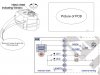
Closing the Valve: Power applied to the "Power Terminals" on DPDT only will close the water valve. This power sources must have a min amp capacity of 300 milliamp for the KLD20S or 1600 milliamp for the KLD100. Possibly sources are either a Relay Output on an Alarm Panel or Separate 12V power source.
Opening the Valve: Power Applied to the "Trigger Terminals" on DPDT will trigger the DPDT to reverse to polarity of the water valve, causing it to open
But at the same time power must be applied to the "Power Terminals". The Trigger power source must have a min power source of 60 milliamps and a regular alarm output or alarm relay output would work.


")