Rotary Encoder Programming

Hi Folks,
 
I have 2 webcontrol PLC boards (not updated software) and have used them for various things. I really like the platform, cant beat the price, and overall they have been reliable. This forum has been tremendously valuable to get me going on the programming. Thanks to all!
 
I have one project that has a homemade rotary encoder with 6 pulses per revolution at 22 rpm. It uses a slot sensor with 6 flags on the shaft. I have programming to use a one shot to count the pulses (thanks to rossw post) which works fine in both directions: adding or subtracting from the pulse count depending on direction. What i need is some programming to set an alarm if the encoder fails. For example; if the motor is on and no pulses are occurring. So basically, if the motor is running in either direction (OP1 or OP2) and there is no toggling of the slot sensor (IP7). I have racked my brain for several days and can't seem to get anything working. I usually press though problems on my own to learn better, but this one is really frustrating me.
 
Any pointing me in the right direction is appreciated.
 
Mike
 
Have you tried to enable TTL IP1 as frequency counter?  It will probably read 132 Hz.  When that reading is lowered or stopped, you can send alert.
 
Another way would be to store the current seconds each time you see a pulse, then in your main (supervisory) loop, compare the "last saved" time to the current time. If the difference is more than some number of seconds, generate an alarm.
 
In order to generate an alarm once per hour while stopped, when you send the alarm, overwrite the "last saved" value with the current time plus 1 hour (3600 sec).
(It will automatically clear if the motor starts again, or trigger another email/alarm in an hours time if still stopped)
 
Thanks for your replies gentlemen.
 
CAI: is the frequency counter a function in later generation PLC firmware or do I need to code it? Also, 132 would be cycles per minute not Hz.
 
rossw: not sure how to code that suggestion, I am a hardware and plc ladder logic guy.
 
Warning: the following paragraph may be as clear as mud.......
 
What I do have now is at the bottom of this post and it generally works. It works fine while it is running, ie: the alarm is not set if the encoder is rotating but if I block the sensor the alarm is set and if I remove the flags (unblock the sensor) the alarm is set. so far so good. HOWEVER, the IP delay does something I do not expect. What I would expect is if the timer never exceeds the value, the "TSTEQ IP7[1500] X" statements will not get executed, but as soon as I shut the motor off for more than the timer value the alarm is set immediately on the next start.
 
I don't think its my motor program, I did a simple  test program and the IP delay does the same thing.
 
START    
    TSTEQ IP4[3000] 1  **check if IP4 is on for 3 second or more
    SET OP8 1               **if true set op8 to 1
    TSTEQ IP5 1            **check if ip5 is 1 (reset)
    SET OP8 0               **set op8 back to 0
    NOP    
    END  
 
In this case I reset OP8 and immediately start making IP4 for less than 3 seconds repeatedly; OP8 is never turned on: this is what I expect. If I make IP4 for longer than 3 seconds OP8 comes on: also what I expect. If I repeat the whole process, and just wait for over 3 seconds AND THEN make IP4, OP8 immediately comes on. That's what I don't understand.
 
I have read other posts about IP delay issues and possible fixes in later firmware. Is it my v03.02.07  firmware or am I not understanding input delay?
 
Thanks,
 
Mike
 
 
__________________________________________________
Current encoder failure program section
 
START    
    TSTEQ IP1 1                    **reset button 
    GOTO RSTALRM   
    TSTEQ OP1 1                  **motor CW
    GOTO CHECKENC   
    TSTEQ OP2 2                  **motor CCW
    GOTO CHECKENC   
    GOTO DONE   
CHECKENC:
    TSTEQ IP7[1500] 1          **check if encoder on for more than 1.5 sec
    GOTO SETALARM   
    TSTEQ IP7[1500] 0          **check if encoder off for more than 1.5 sec
    GOTO SETALARM   
    GOTO DONE   
SETALARM:
    SET OP8 1                       ** set alarm output
    SET OP1 0                       ** turn off motor CW
    SET OP2 0                       ** turn off motor CCW
    GOTO DONE   
RSTALRM:
    SET OP8 0                       ** reset alarm output
DONE:
    END   
 
I'd probably do something like:
 
 
Code:
start:
   set ram1 CS  ; current time in seconds
main:
  xor ip1 ram2 ram2 ; input 1 changed state?
  bnz start   ; input changed, reset timer
  sub CS ram1 ram3  ; take last change time from current time
  tstlt ram3 2 ; is it less than 2 seconds?
  goto main  ; yes, do nothing.
  email em1   ; trigger an alarm
  add CS 3600 ram1  ; set alarm again in an hour if still broken
  goto main
 
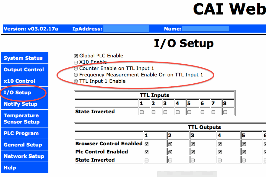
Frequency counter is in for some times. If you go to "IO SETUP" tab, you can see if there is a frequency measurement enable. That is per second. WC8 can measure up to 2MHZ frequency, to the low end, it can measure 60HZ(like AC power) or lower frequency reliably, updated at least twice per second.
 
If your board hardware is V2.2.2 with older firmware not having this feature, you can always send it in for update with latest firmware with bootloader.  We only charge a minimum fee to cover handling and shipping. In the future you can load new firmware with easy.
 
Hi BraveSirRobbin,
 
We can not post any screen capture on this due to our account is limited. However, if you login into WC8 board, on the left hand side, you will see a "I/O SETUP", click on that, on top of that screen, it will have "X10 Enable", then "Counter Enable", then next is "Frequency Measurement Enable".  Please note TTL one can only be functioned as one of those three: Counter input, Frequency Measurement Input, or IP1 input.
 
CAI_Support said:
We can not post any screen capture on this due to our account is limited. However, if you login into WC8 board, on the left hand side, you will see a "I/O SETUP", click on that, on top of that screen, it will have "X10 Enable", then "Counter Enable", then next is "Frequency Measurement Enable".  Please note TTL one can only be functioned as one of those three: Counter input, Frequency Measurement Input, or IP1 input.
 
Here's a screen cap showing what Wayne couldn't post:
 
wc-countersetup.gif
 
rossw,
 
Are you the same rossw on thebackshed.com? Thanks for your help here. I added your code and it works for ip1 fail low but not fail high. "xor ip1 ram2 ram2" evaluates as F,F,F,F,F,F,F, for each successive scan during fail low but T,F,T,F,T,F,T,F for fail high so it never gets to complete the 2 second timer.....unless I am missing something......
 
I have tried in vain to come up with a fix, but to no avail. Any ideas?
 
Also, does anyone have any comments on the input non blocking delay funkyness I am seeing as I related above?
 
I am sending my boards back to CAI for the firmware update after I get back from a trip. I am impressed with their response to email and this forum. Great product support!
 
Bassmanisme said:
Are you the same rossw on thebackshed.com?
 
Yes, although I haven't been there for many years. I had a difference of opinion with someone who considered windows was the only operating system worth using, and microsoft were the source of all good in the universe.
 
 
Bassmanisme said:
Thanks for your help here. I added your code and it works for ip1 fail low but not fail high. "xor ip1 ram2 ram2" evaluates as F,F,F,F,F,F,F, for each successive scan during fail low but T,F,T,F,T,F,T,F for fail high so it never gets to complete the 2 second timer.....unless I am missing something......
 
I have tried in vain to come up with a fix, but to no avail. Any ideas?
 
I may have had a brain-fart :)
I did say it hadn't been tested ;)
 
Try this instead.

Code:
start:
   set ram1 CS  ; current time in seconds
   set ram2 ip1  ; read input
main:
  xor ip1 ram2 ; input 1 changed state?
  bnz start   ; input changed, reset timer
  sub CS ram1 ram3  ; take last change time from current time
  tstlt ram3 2 ; is it less than 2 seconds?
  goto main  ; yes, do nothing.
  email em1   ; trigger an alarm
  (and do other alarm type things here)
  add CS 3600 ram1  ; set alarm again in an hour if still broken
  goto main
 
Thanks Ross. I'll give it a try when I get back from my trip and let you know how it works.

At the risk of derailing my own thread, are your polar mount solar trackers still working? Have the shaft and metal blocks held up to the weather and wear without bearings? Anything you would change?

Thanks again!

Mike
 
Bassmanisme said:
Thanks Ross. I'll give it a try when I get back from my trip and let you know how it works.

At the risk of derailing my own thread, are your polar mount solar trackers still working? Have the shaft and metal blocks held up to the weather and wear without bearings? Anything you would change?
 
 
Yes, they're still running fine, although they're not really polar. (similar, but not quite!).
I'd use different actuators, these ones don't like the conditions very much and I've had most of them fail. So far I've reserected most of them in the workshop, but two needed replacing.
I also needed to weld some additional stabilizing legs low down on the posts, and put more concrete around them. That was not a problem with the tracker though, but with the ground they were set in.
The webcontrol that's running them is still just chugging away fine.
 
Hi Folks,
 
First thanks RossW for your help on this.
 
Second, I sent my boards back to CAI for firmware upgrade and my input non-blocking delay problem (described above) is gone. The input delay now works as I expect.
 
Thanks!
 
Mike
 
Back
Top