Help please: replacing 3-way switches with z-wave

rogersmj

Member
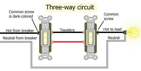
I've got a 3-way circuit wired like the below (I know this for sure):
 
https://www.evernote.com/shard/s2/sh/d124bd93-7cdb-414c-87e4-caaad63f70a3/ccfa3e3f2b0dd6118b4fbaa510aa3751
 
I have a Linear Z-wave dimmer (line, load, neutral, ground) and a Linear z-wave accessory switch (line, neutral, ground).
 
I'm trying to figure out how to hook these switches up, given the wiring I've already got in the walls. In the primary (dimmer) box, I think I need to tie together the black and red (to the load) wires, and then tie the white (taped) and black in the secondary box in order to form a complete circuit. Otherwise I have no way of actually providing a load to the dimmer switch directly.
 
The next question is how to hook up the accessory switch. It needs its own source of power and a neutral. I actually have a neutral from a different circuit in the secondary box due to the fact that it is shared with another 3-way that goes up the stairs (I understand this is semi-common thing). Can I tie into that? Where can I get power from for the accessory, hijack it from that other 3-way maybe?
 
That is the strangest 3-way wiring I've ever seen.  I'm still trying to figure out how it works, and not getting very far.
 
Both down: First switch has isolated the feed line, so nothing's happening
First Down, Second Up:  same
 
First Up, Second Down:  12/3 #1 has black hot.  12/2 top has black hot, 12/3 #2 has red hot with no neutral.  Red hot is connected to white at switch #2, so white is hot in 12/3 #2, feeding white hot 12/2 top, feeding red hot in 12/3 #1, which is isolated by switch #1.  Huh?
 
First Up, Second Up:  12/3 #1 has black hot.  12/2 top has black hot, 12/3 #2 has red hot with no neutral.  Red hot is connected to black at switch #2, which energizes both lights.
 
So this is some really weird way to require BOTH switches on for the circuit to work?  Is that right?  If so, this isn't really a three-way switch.
 
Depending on how you really want this to work, I think you're going to need to rewire the light fixtures as well as the switches.
 
+ 1 FlyingDiver
 
Typically an aux switch utilizes conventional 3-way wiring methodologies.  You can too create a virtual 3-way with two of the same switches.
 
Your drawing doesn't indicate (its assumed but not labled) the traveler for the aux switch and a ground wire (neutral (white), hot (black) and green (ground) plus a traveler.
 
Personally I would:
 
1 - flip the breaker off and disconnect primary hot source on the left. (bring in a lamp from another room to light up your view)
2 - Disconnect everything (switches and lamps)
3 - Use a VOM to trace and label the wires (for yourself temporarily).
4 - you have 3 wires plus ground going across - switch to lamp to lamp to switch.
5 - 3rd wire across would be your traveler. 
6 - White neutral just connects to everything automated (switch, lamp, lamp & switch) only the lamps in legacy switch mode.
7 - hot - black wire is just that.  the two lights have a switched hot lead plus an always connected neutral (well and ground).
8 - baby steps and don't make assumptions based on the colors of the wires until you have validated them with a VOM.
 
Here is a drawing which is labeled.  Best to VOM check each wire. 
 
You know what colors are supposed to be; but validate them anyways.
 
Here the electrician went to yellow travelers and blue wires from the switch to the lamp.  Most of the rooms have ceiling boxes and two or more switches plus 1/2 of the outlets are switched (with is a bit of a PITA to deal with).
 
Think analog switch wiring first; then the automated switch / AUX combo secondly. 
 
The AUX combo is meant to be utilized with analog wiring.
 
Personally I went to virtual 3-way automated switching; but that is me (and capped the travelers). 
 
The second (or 3rd or 4th) switch remote controls the primary with a load switch.
 
3-way-circuit-450.jpg

 
Here the multipaddle / dual load UPB switches are direct, virtual (3 way), scene or just automation "do what" mini paddles.
4-rocker_config%20-%20a.jpg
 
Thanks guys. Yes I agree it's weird, but somehow it works normally with standard 3 way switches.
 
I don't have the option of disconnecting/rewiring the lights; they're recessed pre-construction (not reno) lights, the wiring is not accessible.
 
My aim is to do virtual 3-way, so I just need to get the primary box wired into the lights like a normal switch, and then somehow have full-time power in the second box.
 
To achieve goal #1 -- allowing the dimmer I plan to put in the first box to control the lights as it normally would in a 2-way config -- I have to get the "load" connected. Since there is no direct connection to the black terminals on the lights from the first box, I'm thinking I'm going to tie the red and black in the second box together, which will then allow me to use the black in the first box as the "load", as I would in a normal switch. Right?
 
I'm going to have to experiment with how to achieve goal #2, getting the aux switch full-time power in the second box, but I think I can do that by tapping into the line coming off another three-way switch I have in that box.
 
This looks pretty standard to me. Unfortunately, I dont think you will be able to get neutral at the second box without changing some wires at the fixture.

Using a neutral from the other circuit and hot from the first circuit would be a code violation due to a risk of too much current on that neutral. However, if you have both supply and neutral from another circuit in the same switchbox, I expect you can make this work.
 
If you are calling primary the box on the left in your diagram where the power enters, the answer is:

1. Install the remote/accessory switch in the primary box.
2. Use one traveler wire to feed power from the primary box to the secondary box.
3. Use the other traveler wire to feed neutral from the primary box to the secondary box.
4. Install the load control switch in the secondary box.
 
oberkc said:
This looks pretty standard to me. Unfortunately, I dont think you will be able to get neutral at the second box without changing some wires at the fixture.

Using a neutral from the other circuit and hot from the first circuit would be a code violation due to a risk of too much current on that neutral. However, if you have both supply and neutral from another circuit in the same switchbox, I expect you can make this work.
 
And that's what I wound up doing. I got the dimmer working by itself in box 1 by tying together red and black in box 2. Then I used the hot and neutral from the other switch in box 2 (on a different circuit) to power the aux switch.
 
If I wouldn't have had that other line/neutral feed in box 2, though, I'm not sure what I would have done.
 
az1324 said:
If you are calling primary the box on the left in your diagram where the power enters, the answer is:

1. Install the remote/accessory switch in the primary box.
2. Use one traveler wire to feed power from the primary box to the secondary box.
3. Use the other traveler wire to feed neutral from the primary box to the secondary box.
4. Install the load control switch in the secondary box.
 
Ah, good thinking! Yes, that probably would have worked for pretty much any other instance, although in this particular case my secondary box is a shallow box (in a furred basement wall) and the accessory switch barely fits. The dimmer switch probably wouldn't have fit, so my only choice was to put it in the primary box.
 
Thank you all.
 
my secondary box is a shallow box (in a furred basement wall) and the accessory switch barely fits
 
Curious what is the depth of this shallow box mounted on/between a furring strip?
 
While I have mostly UPB I still do have wireless X-10 keypads around which literally have a very thin footprint. 
 
Mostly house is using UPB in wall lighting switches; still have a few X-10 wireless pads around tacked on to walls that work fine these days (batteries last forever in these thin footprint devices).
 
Does a wireless Z-Wave scene switch with a thin footprint (which would be 120VAC powered) exist?
 
I've attached a standard Z-Wave switch drawing.
 
ViziaRF+-switch-drawing-dimension-3.jpg
 
pete_c said:
Curious what is the depth of this shallow box mounted on/between a furring strip?
 
 
Does a wireless Z-Wave scene switch with a thin footprint (which would be 120VAC powered) exist?
 
I've got it all closed up now, but I think it's just shy of 1.75" deep. I use all Linear z-wave switches, because their dimmers by far work the best with LED loads and as a bonus they're cheaper than most other switches (about $40 per). It fits in that box, but barely, and only because the switch next to it is non-zwave so I was able to cram most of the wire nuts behind it, rather than behind the z-wave switch.
 
Yup; had a heck of time fitting two automation switches inside of a metallic 4X4 box (well it was the wires and the physical footprint of the switches).  On another endeavor (LED landscaping lighting) I could only fit a UPB switch in a metal box / metal cover by trimming the metal on the switch (which you cannot see and it looks OK).
 
Curious then if you used spacers to flush level the two switches and if you used a deeper wall switch plate cover?
 
Noticed that one higher load / amperage UPB switches (analog light loads versus LED light loads) have larger heatsinks and a custom wall switch cover while another one on another floor is paired with a conventional analog switch with a regular wall switch cover.  ( thinking one is a PCS UPB switch and the other is an HAI UPB switch)
 
Back
Top