Help to connect SSR

nitin100

Member
Please help in connecting the SSR to TTL outs of CaiWeb.
 
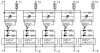
The SSR is common anode, ie, it has one + and number of - (Its a five channel SSR)
PN5-10DA. The spec sheet is available freely(please google and you may be directed to alibaba page - but that contains the internal diagram) and I can see that its optically isolated, with common anode.
 
How do I connect this SSR to TTL outs(1-5) of webcontrol.
 
Thank You
Nitin
 
Yes -I have seen this picture. The question is how to connect.
As per the picture, it looks like the trigger is -ve logic with common anode, ie, when voltage drops below 0v, the SSR will trigger.
 
But webcontrol is +ve logic, with common ground.
 
Should I connect pin 9,10 of webcontrol TTL out to pin + of PN5 and pin 1-5 of TTL out to Pin -1 to -5 of PN5?
 
Nitin100,
 
You are correct, the SSR you refer to us negative going to turn on.  You will need to add an transistor to change its input polarity, so that when input is 0V, it will remain open. When input is TTL 1, switch on the SSR,  The transistor must stay close to the SSR, so that if SSR lost power and power restored, it will not mis-fire the output side.
 
This one is also SSR relay, and it is positive triggering:
 
Code:
http://www.amazon.com/SainSmart-8-Channel-Duemilanove-MEGA2560-MEGA1280/dp/B006J4G45G
 
Please people,  these are not "negative triggered".
Common anode does not require "negative voltage" nor "voltages below zero".
It only requires the anode be more than the minimum voltage above the cathode.
If that means the Anode must be at +5V, the cathode only needs be from 0 to 2V to meet the specification.
 
"Active low outputs" to operate it, sure. That I would agree with.
Is it ideal for use with the WebControl board? Certainly not as it stands, for the reasons CAI highlight (mainly safety).
But it CAN be used perfectly fine in a 0/+5V environment WITHOUT the need for "negative voltages".
(I know this may seem petty, but it's a specific difference and actually important)
 
rossw said:
Active low outputs" to operate it, sure.
I was reluctant to jump in and make this even more confusing to the OP but:
 
SSR's are current driven. That means as Rossw posted the - terminal must be more negative then the +. If you connect an SSR to the WebControl and it looses power and you have powered the SSR from a different supply the SSR will not get turned on because the WC is unable to sink any current so the - terminal will be at the same potential as the + (lets ignore diode drops).
 
Now if instead of directly connecting it you buffered the WC with a logic gate to provide more drive current to the SSR or relay it may get turned on if the WC loses power because the gate input voltage will be at  a low level .
 
The other thing one needs to be aware of (at the risk of confusing the OP even more) is power up/power down and what happens to outputs. The way to guard against this problem is to use some form of external logic, that has a predictable output state at a low enough voltage to prevent the output from spuriously turning on during power up and power down. The WC outputs are a good example. I assume the Microchip processor I/O can be programmed to be inputs or outputs. The WC output are initially high and then once the micro-controller stabilizes they go low. If that is a problem in your design need to guard against it occurring.
 
There are many other considerations, it all depends on how exciting life gets if your widget does not operate as expected on power cycle or has some kind of run time failure, either hardware of software.
 
/tom
 
The problem is during WC8 power restored, during its power up, its output are TTL 0, which will sink current and will cause active low relay trigger.
We always want to advise users pick TTL1 triggered, so that if you have 8 motors controlled by 8 TTL outputs, they will not start turning during power up.
 
If you already have a TTL0 triggered relay board, one way to use them is to have a SSR controlled by WC8 output, it will only turn on power to relay board when PLC telling it to do so.
 
I ended up with some active-low triggered relay boards, in spite of assurances and even a schematic emailed from the ebay seller in China.  Their response when I complained wasn't much more than "oops".
Anyway, I added a Darlington transistor array ULN2803Ahttp://www.ti.com/product/uln2803a to my design to give me hardware-inverted outputs, and that has worked fine.  It takes up less space than individual transistors and I can choose to use the inverted output or not by coming off of the input or the output side of the chip.  It is overkill for TTL levels, but it works.  In addition to two dual-relay boards (4 relays), I'm actually controlling power to a matchbook-sized router (Edimax BR-6258n) off of one of the Darlington array outputs (directly, without a relay).
 
-Ben
 
CAI_Support said:
Ben,
 
That is nice.  Maybe you could post some pictures of your mod and wiring to that little wifi router.
 
Thanks.  Next time I've got it open I'll try to remember to snap a picture.  It's out in the chicken coop, opening the door in the morning and closing it at night.  I'll soon add control of the light to keep their day long enough that they don't stop laying eggs in the winter, and heat for the water so it won't freeze.  It will also warn us when the food or water levels are getting low. 
 
bgriffith said:
Thanks.  Next time I've got it open I'll try to remember to snap a picture.  It's out in the chicken coop, opening the door in the morning and closing it at night.  I'll soon add control of the light to keep their day long enough that they don't stop laying eggs in the winter, and heat for the water so it won't freeze.  It will also warn us when the food or water levels are getting low. 
 
interesting, why the most usable products end up in individual applications whist millions of scrap relay boards are on all sale channels... I'm back with my wish that CAI sets up a portal offering all the periphery one needs for professional use of the WC.
 
"most usable products" -- the SainSmart relay board triggering by active low signal does not work for WebControl, if the load is critical machinery. This also apply to Rx Pi boards and many processors. Users of Pi board have same problem WebControl users have.
 
We think your suggestions is a good one, maybe you can talk to your local suppliers about that idea. We are busy with development and adding functions and features. We do not want to put our finger into other people's business.
 
Hello
Good that the question I raised a lot of other questions - Which I and others might have faced later.
 
I am switching to individual relays(ie, no common anode cathode) which should work. Will update on this thread if it doesnot.
 
Just a heads up. If you are using individual relays will need to buffer the WC output to increase current capability. You can use individual transistors or a transistor array, which is just a bunch of transistors (typically Darlingtons) in a single package.
 
If the relay or transistor array does not have a built catch diode will need to add one. The purpose is to clamp the high voltage generated when the switch opens and the magnetic field collapses.  Think automotive ignition system as an analogy.
 
/tom
 
Back
Top