Good morning,
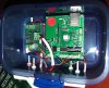
I used the following schematic to make a 12VDC to 9VDC converter, which worked perfect (see attachment).

Since I need both 12VDC and 9VDC for my project (12V to run a motor, 9V to run WC8.0), I could simply tie off the 12VDC input of the converter (see second attachment).
This, however, caused a periodic flip flop of the 12V OUT as if the caps had an impact; which shouldn't happen since I tapped off the 12V before the circuit using the caps.

Where am I going wrong?
Rainer
I used the following schematic to make a 12VDC to 9VDC converter, which worked perfect (see attachment).
Since I need both 12VDC and 9VDC for my project (12V to run a motor, 9V to run WC8.0), I could simply tie off the 12VDC input of the converter (see second attachment).
This, however, caused a periodic flip flop of the 12V OUT as if the caps had an impact; which shouldn't happen since I tapped off the 12V before the circuit using the caps.
Where am I going wrong?
Rainer
")