Welcome to Cocoontech xyzzy.
Here is a little chart relating to the standards of 1-wire RJ-11, RJ-12 and RJ-45.

Here is a nice document relating to an overview of
1-Wire stuff.
Personally here went with my own RJ-45 standard based on using two or three wires back in the early 2000's separating the networks based on 5VDC or 12VDC and initially using a star topology then later a hub and spoke star topology.
Utilizing a hodgepodge here of Temp05, Temp08, HB and Maxim hubs.
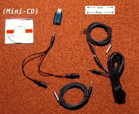
Relating to the RPi2 have one setup using a USB mini hub that utilizes 3 wire stereo mini audio plugs (3 wires). I cut the wires to utilize a combination temperature / humidity sensor.
Another that is using the GPIO pins with a pull up resistor or using a DS-1307 mini RTC clock board with additional pins for 1-wire sensors (specifically used a DS-18A20). The three pins on the top left are for a 1-wire sensor. The board is around $1 on Ebay. Its been a while here that I have purchased DS-18A20's in bulk for less than 1 penny apiece.
The GPIO methodology is just a bit of bit banging and now sort of a standard along with the older standard of the Maxim to RS-232 to USB stuff. Either way works fine today.
On the RPi2 I output the stuff for the 1-wire sensors in the same format whatever methodology I use to get data.
This stuff is from a POE connected RPi2 in the attic running Homeseer 3 automation software. The device is doing Z-Wave plus (via GPIO card), X10 and UPB (via networked remote controllers).
Linux ICS-RPi2-Zee 4.1.13-v7+ #826 SMP PREEMPT Fri Nov 13 20:19:03 GMT 2015 armv7l
Last login: Thu Feb 18 01:31:48 2016 from 192.168.244.236
Uptime: 31 days 19 hours 44 minutes
CPU Speed: 900 Mhz - Load Average: 1min 25% 5min 27% 15min 28% - Cores: 4
Free Memory: 669 Mb
Free Disk Space rootfs: 7.1G
SD Card: Written 27782M Read 0G
Network Traffic eth0: Sent 682.3 MiB Received 1.2 GiB
~# cat temp
Feb 19 07:04:02 Sensor 0 C: 8.88 F: 47.97
Feb 19 07:04:03 Sensor 1 C: 8.19 F: 46.74 H: 71%