Lighting control question

Ira

Active Member
New construction. Electrical rough-in starting soon. The scenario is...
 
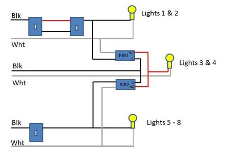
I have eight recessed light cans (haven't purchased them yet, so don't know what kind), all in fairly close proximity to each other, but not exactly in the same room. Lights 1 and 2 are controlled by the same 3-way switch setup. Lights 5, 6, 7, and 8 are controlled by the same single switch. I need lights 3 and 4 to be on if 1 and 2 are on, and/or 5 thru 8 are on. If 1 and 2 are off, and 5 thru 8 are off, then 3 and 4 should be off. I guess you could say that 3 and 4 "overlap" with the other two groups of lights.
 
I haven't considered any kind of "smart light" setup, UPB, etc., although I need to look into lighting control very soon. Is there a conventional wiring solution to this, or does it require some level of smart lights and/or home automation? I will be installing an Elk M1G, but I've never used it for lighting control.
 
Thanks,
Ira
 
This would be easy to do with just two RIB relays. Connect the coil of one relay to the neutral and switched hot wire for lights 1&2. Connect the coil of the other relay to the neutral and switched hot wires for lights 5-8. The common terminal of both relays gets wired to the always-hot wire for lights 3&4. The normally open (NO) contacts of the two relays get wired together for use as the switched hot to lights 3&4. Just a simple OR circuit.

You need to keep the neutral and hot wires for each set of lights together in the same cable to be compliant with the NEC.

You'll need to locate the relays on a junction box that is accessible in the future, in case they ever need replacing, or if the wiring connections need repair. You can't bury them in a wall or ceiling where you can't get to them. Again, a NEC requirement.

The way things are wired, you could power all the lights from a single circuit breaker, or they could be powered from completely separate circuits. The relays will keep things isolated.

Note that the contacts on this RIB relay are rated for just 600W of tungsten lighting load. With just 2 fixtures for it to turn on/off, that should be fine. If you need to control a heavier load, there are other models of RIB relays.
 

Attachments

  • OR Circuit for Lights.jpg
    OR Circuit for Lights.jpg
    39 KB · Views: 8
Last edited:
With proper smart switches to control each group this would be an easy task for almost any Home Automation system. Not a Remote Control system but actual HA.
 
Insteon and ISY994 would be a known system, but Insteon is way behind on the necessary production ICs inside due to pandemic slowdowns. ZWave is also becoming the popular protocol now and are available in many places. ISY994 can handle that protocol as well.
 
The wiring for the cans and lights is easily accessible from the attic above, and lots of headroom in the attic for mounting the RIB's, so I like the RIB solution. I've used them a lot in the past, but didn't think of them for this. I was hoping this would be easy to do without involving any HA stuff.
 
For the bigger picture... about five years ago, for a different home, I was looking at implementing UPB for some lighting control. Has UPB fallen out of favor?
 
Thanks,
Ira
 
Ira said:
The wiring for the cans and lights is easily accessible from the attic above, and lots of headroom in the attic for mounting the RIB's, so I like the RIB solution. I've used them a lot in the past, but didn't think of them for this. I was hoping this would be easy to do without involving any HA stuff.
 
For the bigger picture... about five years ago, for a different home, I was looking at implementing UPB for some lighting control. Has UPB fallen out of favor?
 
Thanks,
Ira
 
UPB isn't dead yet, but I think it has lost the battle for marketshare against z-wave.   You can pick up a z-wave switch at Home Depot or Lowes, but have to pretty much get any UPB stuff by mail order. 
 
I prefer using inexpensive relays vs UPB or Z-wave switches anywhere I can if I don't require things to be automated or future flexibility.   No worries about them dying from a power surge or issues with them not working now and then due to interference
 
I recently made the switch to using wifi "smart" switches and plugs that are compatible with a third party firmware called "Tasmota".  Not every wifi switch/plug being sold is compatible, so you have to do your research before buying.  Still, these devices are relatively cheap ($20 or less usually) especially compared to other lighting systems and the Tasmota firmware is great.  It removes all dependence on the internet for one thing - my switches are fully functional without having any internet access.  Secondly, you can program a lot of automation right into the devices/firmware.  It is very simple to program the devices to turn on other devices and it would be very easy to program the "automation" you are looking for.  The advantage to this is that it is completely self-reliant.  You don't have to run the automation on another system or device that must be functioning in order for the lights to work as expected.  As long as the lights have power, they will work as intended because the programming is built into the device.  Now these devices can also be tied into a larger automation system as well, but it is really nice to be able to program the devices with basic lighting automation and then let the "larger" automation system also control the lights as needed.
 
In my house, we have a large open space that has can lights controlled by two different switch circuits.  I installed these Tasmota flashed switches at the three switch locations (one was a 3-way originally and the other a single switch) and programmed them to all turn on/off both sets of lights whenever any of the switches are changed.  I also have some switches in the kitchen that have dimmer up and down buttons and have programmed the dimmer buttons to actually turn on/off the under counter LED lights which are actually plugged into a wall socket in one of the cabinets with a Tasmota flashed plug to control it.  The same goes for some sofa lights in the Den.  The den wall switch controls the ceiling lights, but the dimmer buttons have been programmed to control the sofa lights.  I also have several light switches to control outside floodlights.  Originally each switch controlled just one light and the switches were located on opposite sides of the house.  Now I have them programmed that every switch will turn on/off every light. All of this "automation" is programmed into the Tasmota firmware and works independently of my larger automation system.
 
PS - I use switches from a company called Martin Jerry.  They make several models (some single switches, some three-way switches, some dimmer models, some non-dimmer, etc).  Here is the one way dimmer model I use since I mentioned the extra buttons I use on it.  https://smile.amazon.com/Martin-Jerry-SmartLife-Dimming-Assistant/dp/B07FXYSVR1/ref=sr_1_1?dchild=1&keywords=martin+jerry+dimmer&qid=1632763060&sr=8-1
 
Hopefully that gives you an idea of what is possible with the Tasmota flashed wifi devices.  
 
I agree with RAL about using more conventional methods (like relays, various wiring techniques, etc.) when possible. Having never done HA lighting control, I'm not sure what we would want/like, so I want to take it slow and approach it after we are in the house.
 
Another question about this if using the wiring previously posted by @RAL ...

Assume I'm using the appropriate dimmers for both sets of recessed lights, e.g., the Lutron Diva dimmers that work with LED's. Both switches are off. The dimmer for lights 1 and 2 is set to 100%. The dimmer for lights 5 - 8 is set to 50% power.

If I turn on just the switch for lights 1 and 2, will lights 1 - 4 come on at 100% brightness?

If I turn on just the switch for lights 5 - 8, will lights 3 - 8 come on at 50% brightness?

If both switches are turned on (dimmers are still at 100% and 50%), what brightness level will each light have?

Thanks,
Ira
 
My circuit assumed just a simple on/off switch and not a dimmer. Since the relays are powered by the output of the switches, they might not be happy with the chopped output from a dimmer.

As the circuit is drawn, the shared lights (3&4) are not powered through either switch's output. So if the switches are dimmers (and assuming the relays work with the dimmer's output) and dimmer-1 is set to 50%, lights 1 and 2 will come on at 50% and lights 3 and 4 will be at 100%.

The relay wiring could be changed so that the "C" terminal of each relay is connected to the output of it's controlling switch. Then, if you turn on only one switch, lights 3 and 4 will come on at the same level as the other lights controlled by that switch.

If the dimmers are triac type dimmers, and you turn on both switches, the output of both switches will be connected together and all the lights will see the combined output. With simple triac dimmers, the brighter setting will win. So if one dimmer is set to 50% and the other to 100%, all the lights will be at 100%.

The Lutron Diva dimmers are triac dimmers according to the Lutron spec sheets. Still, you might want to check with Lutron to see if there would be a problem with them operating in parallel. It wouldn't surprise me if they tell you don't do it because they've never tested it.

[Edit]:

After thinking about this a bit more, the two relays could be replaced by one SPDT relay with both normally open and normally closed contacts. Only one of the light switches would activate the relay, and switch the control of lights 3 & 4 from one switch to the other. This would eliminate the outputs of the two dimmers being placed in parallel and would allow the two sets of lights (1&2 and 5-8) to always be at the setting of their own dimmer. When only one switch is on, lights 3&4 would be at the same setting as the dimmer that is on. But if both switches are on, then lights 3&4 would be at the setting of the dimmer that you choose to have priority. For example, they would always go with the brightness level of dimmer 1 when both switches are on (if that's what you prefer).

The downside of the single relay is that if both switches are on and one dimmer is then turned off, lights 3&4 would blink for a split second and also change in brightness as the relay changes state.
 
Last edited:
I think I can use a variation of the design @RAL provided. These particular lights (Halo LED wafer lights) won't be "ambiance lights" that will be dimmed/brightened on a regular basis. The lights don't have adjustable brightness, so we will be kind of stuck with what we buy. If a 4" light isn't bright enough, but a 6" is too bright, my plan was to get the 6" lights and use dimmer switches to dim them to the desired brightness. My guess is the lights will seldom be turned up or down after that.

I can put non-dimmer switches at all switch locations. Each of the two switch legs will go two places, in parallel. The switch leg that controls 1 and 2 will go to the relay, as well as a dimmer mounted in the attic, in parallel. From the dimmer, I can go to the drivers for 1 and 2. The dimmer will always be on, and will only be used to set the light level for 1 and 2. The other cable goes to the relay with full power. Same for the switch for lights 5 - 8. Switch leg coming from rocker switch goes to another dimmer (then lights 5 - 8) and another relay, in parallel. The output of the two relays goes to a third dimmer, which sets the brightness level for lights 3 and 4 when they are on. The relays only see full power at the coil and contacts.

If it turns out that "dimming on demand" is required, I can replace the three dimmers in the attic with smart dimmers, and control them from a phone or another switch. I guess I could even replace the rocker switches with smart switches and let them control the smart switches in the attic, e.g., a double tap would set them to 50% power.

Thanks,
Ira
 
Back
Top