Tips/Advice for Panel Layout

viroid

Member
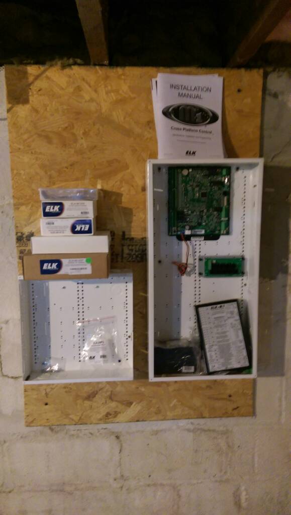
Hey folks, I've been lurking for a few years now, managed to pickup some Elk components under the guise of a security system during a whole house renovation project this past year (It literally took me a year.. ) and I'm finally ready to land some wires. I was hoping that I could impose upon some of you for tips and or advice on laying out panel(s). I'm a bit OCD, so this will end up looking more like a work of art than a security/ha panel, but I dont want to cut anything until I have a plan. I'm thinking about terminating all of the field wiring on terminal strips in the smaller panel and then pulling jumpers across to the inputs in the larger panel. Or perhaps using the smaller panel for batteries (I think I only need one.) and only using terminal strips for power distribution to field devices within the main panel. I'm a bit fond of that slotted raceway, I suspect it would make my OCD quite happy. I have two panels, a handful of boards, and lots of wires. Elk M1g with two XIN, XSP, EXP, DBH, and an SA DB9 Interface Module. Home runs to; 18x Windows 9x Motion 9x Doors 8x Glass Breaks 2x Keypads 2x Interior Speakers.
 
 
f3d862ee097449ed1fab91fe048ff330.jpg


...v Sent from my HTC One_M8 using Tapatalk
 
I used slotted raceways at my previous home and really liked the result.  It's very versatile and easy to add/change in the future.
 
I have some pics on my blog.  I could have done a LOT better job in running the wiring to the zones on the main panel (left side) using wax string and taking my time with sizing and bending the wiring.
 
I also use the 'slotted raceways'.  Works well and flexible.  I just used a few remaining sections of the raceway for my rack cabinet wiring.  The Panduit brand raceway is expensive.  I located a knock-off brand that worked fine.
 
I contemplated, and dismissed, the concept of terminating field wiring on some type of terminal or punch block...   Extra connection points reduce the reliability of the circuit.  Just terminate the sensor/field cabling on the I/O points on the M1 or expander board.  For future-proofing, I leave the field cabling long, and coiled the excess in the ceiling above the panels.
 
The M1 battery leads more-or-less determine the placement for the battery.  I don't all of the code specifics, but the battery leads are not a 'power limited circuit' and need to remain isolated from field wiring.
 
Good luck and have fun!!
 
There is a minimum distance the battery needs to be from the main panel.  I forget what that is but I'm sure others will know and chime in.
 
I agree and would also forgo the terminal strip landing and wire at least all the zones directly into the panel.
 
BraveSirRobbin said:
I used slotted raceways at my previous home and really liked the result.  It's very versatile and easy to add/change in the future.
 
I have some pics on my blog.  I could have done a LOT better job in running the wiring to the zones on the main panel (left side) using wax string and taking my time with sizing and bending the wiring.
 
What is the wax string used for, simply pulling wire?
 
 
...v
 
Cable 'lacing'.  The art of bundling and tying the bundles.  I use plastic cable-ties myself.  They can't be untied and reused, and more than once I've wrapped a bundle only to see that I missed a cable or two...  But I buy cheap ties.  Homedepot often has a large canister of various length ties for a less than $10.
 
BraveSirRobbin said:
There is a minimum distance the battery needs to be from the main panel.  I forget what that is but I'm sure others will know and chime in.
 
I agree and would also forgo the terminal strip landing and wire at least all the zones directly into the panel.
No minimum distance for M1 to battery. Separation only applies to the unfused battery leads and LV cabling.
 
Look at the Elk pictures. Use SWG's for everything that can support them and don't worry about laying the boards flat.....I'm definitely not a fan of that method using a M1.
 
Don't go the route of a terminal strip and jumpers. Adds failure points, complexity and honestly, just what ends up being a mess in most systems. We're not talking huge installs here with a maxed out M1 or multiples (that's a fun proposition).
 
XEP gets typically installed top right next to M1 serial on SWG's. I like running power through OUT 3 on the board and cut the wall wart off and grab power from the M1 or aux supply.
 
Battery typically on a shelf under the M1. Either left or right of enclosure. In your case, with the hub, I'd probably go LEFT under the M1 and then put the hub to the RIGHT.

I typically would install an Elk 950 to the right under the M1. Probably between your hub and the M1 in this case.

Expanders and other boards would go in the bottom left of the panel, then install on SWG's from L to R (my preference). I usually leave the first "column" of holes in the 28" can open for cable routing and management.
 
I like to bundle my cables by board/plug and then twist the pairs together, then use scrap cable or lace them into bundles to get to each plug section. The lacing or cabling is much more friendly to hands and arms working inside panels. Been sliced by too many ty-raps over the years installed by others.
 
I don't like zip ties for smaller/individual cables, people tend to over tighten them and dent/slightly damage the insulation.  Wax string is good for this.
 
You can use zip ties, but as Del mentioned above, if you don't cut the excess correctly, you will curse many times as you slice your hands while working in the panel.
 
Get a good set of diagonal cutters and take the time to 'flush cut' the excess.  THIS is my favorite set of diagonal cutters.
 
If you can avoid the ability to tighten while removing the tag end, it's better to not use any dikes to cut cable ties. The preferred method (barring a cable tie tool) is to "spin" the tail off the tie using pliers. Actually, the manufacturers started making ties that already are weakened to facilitate this easier.
 
You'll definitely know if you over tighten a cable tie. If you can't spin it around the cables with a little bit of friction, it's too tight. That said, it's not a huge concern unless you're talking data cabling or using the ties as support methods instead of cable management (a no-no for many reasons).
 
You're pulling power for the XEP off one of the three protected power outlets on the left side of the panel, and then passing it through OUT3 (DCR) on the right side of the panel?
 
Why would you pass power for the XEP across a relay?
 
DELInstallations said:
EP gets typically installed top right next to M1 serial on SWG's. I like running power through OUT 3 on the board and cut the wall wart off and grab power from the M1 or aux supply.
 
I typically use one-wrap Velcro for tidying the wiring of my installs; prefer how quick it is to get back into a bundle and add another wire if needed.
 
One home here used a finished closet with two sets of cables prerun.  The top media can was the standard OmniPro 2 can and the bottom media can was a Leviton.  I used one of the rear punch outs for the Leviton Omnipro 2 media can and tested one wire at a time, then used tie wraps there.  It wasn't really a lot of cables and easy to dress. (mostly 22/4 and 22/2 stuff).
 
On the bottom Leviton can I ran the house catXX, speaker, RG6.  There too it wasn't a lot of wires and used velcro to bundle what was in there.  (too a small patch panel  / switch).  I haven't touched or changed anything in some 8 years now.
 
All you see in the closest (it is a closet built a bit deeper than the rest of the house closets) today are the two media panels.  It is in the center of the home.   The wires came down from the attic in to the wall (9 foot ceiling).  I did build a landing platform above the closet with lighting.  I do have to use a ladder to get to the top HAI alarm can.  The LV alarm cabling / wires were pre installed by an alarm installer subcontracted by the GC.  None of the wire was terminated.  It was labeled. I did test each cable before connecting it to the panel.
 
Helped a friend with his LV wiring to panels about 5 years ago.  He put the panel in a section of the basement (9 foot ceilings) that I would call a utility room.  Here the GC left the basement with 2X4's on the cement walls.  It is sort of center of the house above as we used one wall from the attic in the second story down to the area of the panels. The media panels (one is a 42" Leviton can) are mounted on sheets of plywood and the cabling is on the top and will go behind the plywood and in to the media cans from the knock outs in the back versus the knock outs on the top. (just a personal preference here).  I did add a second 120VAC circuit and breaker to the area, plus a light switch box adjacent to the media cans and two porcelain lamp sockets above for a good view of the media cans.  Put a old fashioned wall mount phone plate for mounting an analog wall telephone next to the two media cans.  (I use one here today which is plugged in to the VOIP box).
 
As it is a DIY, take your time doing it....mention baby steps here on the CT forum.
 
viroid said:
You're pulling power for the XEP off one of the three protected power outlets on the left side of the panel, and then passing it through OUT3 (DCR) on the right side of the panel?
 
Why would you pass power for the XEP across a relay?
Ability to reset or cycle power without visiting the panel and can also be accomplished via rules. No different than a remote power cycle on a modem or router....in my case, the relay is there, in proximity to the XEP and "free" as I've normally added a relay board (RB) or XOVR to the bulk of my installs anyways.
 
Back
Top