Can i replace my 7.5 volt wall wart with a 12 volt power supply?

politics123

Active Member
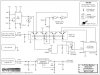
I need a way to replace a 7.5v and 5v wall wart with 12 volts. I have an altronix power supply for my security cameras. It outputs 12 volts (really 13.8), has a battery backup, etc. its also monitored, has protection for ac fail, battery fail, etc. the altronix circuit is also on a whole house universal power supply, but there's a few second lag before the ups kicks in. I like that the altronix battery continues to provide power during the switchover, and also monitors (by way of AC fail) whether the ups is working.

I'd like to hardwire my network gear to the altronix, to prevent a momentary outage while the ups cuts over. I've already plugged in my 12 v wifi routers and telco equipment. However i have two switches, one at 7.5 volts (1 amp) and one at 5volt (1 amp). Both are from trendnet. Any ideas if i can just connect them? The manuals don't give a dc input volt input... How do i know if the switches can handle the higher voltage? (many consumer devices allow a wide range of input voltage)
 
You need a voltage regulator (one for each voltage setting). You can make your own if you are handy, or there are off the shelf setups available. I found this one by doing a quick google search (have no idea how it performs).

Just make sure the converter/regulator can handle the current.
 
Making a 5v regulator is easy, making a 7.5v will probably require a few more parts. You won't be able to use the 7v shed from the regulator, it's burned off in heat. If you go this route, buy a little heatsink for it.

For 7.5 you'd have to make a variable using a LM317 and other parts. I'd put a multimeter in the adapter and make sure it's actually the voltage it claims first. Or just buy a pre-made one like these.
 
I'm not as up on my regulators as I used to be, but I believe you might want to go with an LM150 series for the adjustable given the output current needed.
 
Electronics don't work well after you let out the magic smoke...don't try to feed more voltage than the wall wart or device's power supply is rated for.
 
However i have two switches, one at 7.5 volts (1 amp) and one at 5volt (1 amp).

If you are reading this off of the wall wart, you may be misled. The ratings (current in particular) printed on the wall wart are the capabilities of the wall wart - not the load requirements which are likely much less. If you can't find this in the specs for the load, it is very easy to measure with a DVM.
 
The LM317 as mentioned above is an adjustable voltage regulator capable of one amp output. The LM150 is capable of three amps.

I used an LM317 in my car monitor schematic because I wanted to have a voltage slightly less then nine volts. You can see how it is implemented with the schematic below.

What standon was most likely mentioning was to measure the regulated output voltage (under load) in case you need to make slight adjustments in the ratio of the two resistors (in the case of the schematic below it is the ratio of the 270 ohm and 1.6Kohm resistors).

You need to incorporate an 'adjustable' regulator if a 'standard' regulated voltage is not used. This is why another regulator was mentioned for the five volts as it is 'fixed' for that voltage.

You will need two separate regulators feeding off of the 12 volt for each voltage. You can just get two adjustable regulators as well and just set one to five volts also if desired.

Considering you are at the edge of the LM317's current output, I would recommend the LM150, most likely use the TO220 case for ease of installation. You should also get a heat sink for it. Jameco is a good source for these parts.

Don't forget to fuse each input (before the regulator) also.

One nice thing about a regulator is the front end voltage (in this case the 12 volt source) can vary, but the output will remain constant (unlike the cheaper wall warts).

There are a ton of sites that can suggest other regulation circuits/methodology as well.

Of course, as I mentioned above, there are other alternatives.
 

Attachments

  • carmon.jpg
    carmon.jpg
    97.1 KB · Views: 6
If the current required is anywhere close to 1A (and it may not be as other posters have noted) then the power in a linear regulator like the ones suggested will be high. The losses in the 7.5 V regulator at 1A would be 1A x (12V - 7.5V) = 4.5 W. For the 5 V regulator it would be 7W. This will take a substantial heatsink. For something that is going to operate 24 x 7 I would be very conservative on ratings and derate most things about 50%.

I would look seriously at switching regulators. They are a bit more complicated but will be much more efficient. The battery backup will last longer this way too. National Semiconductor has a "simple switcher" series that have detailed ap notes so very little real design work is needed. Other suppliers have similar stuff.
 
Thanks folks for the help. I have a digital multimeter... but I'm not sure how to use it to measure amps (I assume I'd have to be in series with the power, but my electronics knowledge is a bit rusty. I guess I can dig through my closet and find my kill-a-watt and then run some math to figure out what the DC watts would be.

Let me ask a slightly different question. Don't most electronics have a range of DC voltage that's acceptable? All I know is the DC adapter that shipped with the unit, but I'd bet the switches themselves can handle a range of DC voltage. If I tear open the case, what does one look for to determine what voltage is acceptable?

On more expensive electronics, the manual might indicate "9-12v DC", but on these things, there's nothing printed....
 
If there is nothing printed in the specs, they probably can not handle much under/over their voltage specification.

The manual showing specifications on the product should provide enough data on the current draw.
 
I assume I'd have to be in series with the power, but my electronics knowledge is a bit rusty.

Yes, it's just that easy! Connect in series and set to measure current. Use the lowest range possible to get the best resolution.

Keep in mind that this will give you an average current measurement. Be sure to add a bit and have plenty of capacitance when you design your regulator.
 
Back
Top