BraveSirRobbin
Moderator
[How-To] Automate Your Garage Door
Using Its Wireless Remote Control
by BraveSirRobbin
Many of us would like to control our garage doors (automatic opener), but the lack of wires running from our home automation hardware to the garage area may limit this from happening. This How-To will give you some ideas as to how you can accomplish this goal using your existing remote control (well probably a spare one). The method of monitoring the garage door in this example was "hardwired" but that doesn't mean you couldn't use a wireless method such as the DS10A with a W800 RF receiver or an X-10 power flash module. (I already had my garage door monitored by wiring a magnetic contact switch to my SECU16I (Ocelot add-in module)).
This How-To will not show you any "earth shattering" techniques; rather it will hopefully generate some ideas that may work out for you!
FIRST, the general disclaimer. CocoonTech.com and its staff are NOT responsible for any injury or property damage resulting from anyone using this How-To guide or any associated pictures or links.
My garage door opener is a Genie "Intellicode" model which can use the remote as shown below (purchased from Home Depot).

(Click on Picture for Full Sized Image)
Program the remote to work with your garage door as you normally would (mine required pressing a button on the opener, then pressing the remote within 30 seconds to recognize its code). Also test the remote at the mounting location you desire (e.g. your wiring closet) to make sure it will have the proper range for operating your garage door.
Hey, if you flip the remote over guess what, it has a screw holding it together. Well, you know what that means! Open the victim, err unit up by removing the large center screw and lifting the battery cover. Gently pry the circuit board loose from its case.
Examine the PC board and you will note that the control (push) button is connected to the circuit board via four "feet". Two of these feet are connected together and make contact with the other pair of feet when the button is pressed.
Also note that the battery (at least in this case) is a small twelve volt type. Also note the positive and negative battery terminals (you may have to refer back to the plastic case as the markings of positive (+) and negative (-) were there and not on the PC board.

(Click on Picture for Full Sized Image)
Here is a side shot of the PC board which better shows the "feet" of the pushbutton.

(Click on Picture for Full Sized Image)
The key here is to determine what two contacts can be used on the switch so you can solder a small gauge wire to them and activate the remote when the two wires are touched together. Place the battery in the PC board, then get a small jumper wire and touch two sides of the pushbutton "feet" and see if the garage door responds. If it doesn't try another "pair" of feet with the jumper wire. Once you find the correct pair, short it out with the jumper wire again and make sure the garage door moves in the opposite direction from the first test. Mark these working feet locations.
Now, solder a pair of wires to those feet. I used 22 gauge wire for this purpose as it was easy to pre-tin and hook over the two feet to hold it in place while soldering. Don't use excessive heat or the solder contacts that hold the pushbutton switch to the board will become loose.

(Click on Picture for Full Sized Image)
I really didn't want to have to worry about changing out a battery for this remote once installed. That plus the fact that I already had a twelve volt DC power source powering my Ocelot, SECU16I, and RELAY-8 modules in the same area where this remote would be "mounted" (it's an ELK battery backed 12 volt DC power source). So I just soldered wires to the positive and negative terminals of the PC board and connected their ends to this twelve volt source! Note that this really needs to be DC and I'm not entirely sure the stock ADI wall wart supplied with the Ocelot will provide adequate "DC" regulation. Use at our own risk!
I then connected the other ends of the pushbutton feet to my RELAY-8 module (normally open contacts) as it would provide a "contact closure" via commands from my Ocelot.
After these connections are made, place the PC board back into the remote's case (minus the battery if you are using an external voltage source as shown above). You may have to drill a small hole in the bottom to accommodate the wires exiting the case. Place the screw back in the bottom.

(Click on Picture for Full Sized Image)
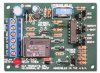
I then mounted this remote in my wiring closet near my Ocelot's Relay-8 module as shown below. Note the Elk twelve volt power source (open box) on the adjacent wall which powers this device as well as the Ocelot and its modules as mentioned above.

(Click on Picture for Full Sized Image)
Now test your newly automated garage door opener with your automation system. Since I used the RELAY-8 module I manually closed the relay (via Homeseer), then opened it after two seconds (you don't want to leave the connection "closed" as it will be constantly transmitting AND you will not have the remote available for any other open/close commands. Your garage door should now be responding to these commands. If not, troubleshoot the system by first pressing the garage door remote's "stock" button (it should still be operational if re-installed in the case correctly), then go from there.
Other brands of remotes will hopefully be as easy to modify as this one. The key here is to locate the pushbutton switch which controls the garage door on the PC board, then try to "extend" this functionality to a pair of wires by soldering to this switch as best as you can. Test the contacts with a short piece of wire first to insure you have the correct ones.
As I mentioned in the beginning I am monitoring my garage door's position with magnetic contacts hard wired to my SECU16I (digital input add-in module for the Ocelot). I use THIS type of magnetic contact switch. They make normally open and normally closed switches, either will work, you just have to get the logic correct.
You can also use a DS10A to monitor your garage door with this magnetic switch (just replace the stock magnetic contact switch supplied with the DS10A with this garage door type). The only problem is you will need a W800 RF receiver and software such as Homeseer to detect/interpret the DS10A.
You can also use an X-10 Power Flash to monitor the garage contact closures as well (will send an X-10 command on an open or close condition).
Another way to control the garage remote (if you don't have a unit such as an Ocelot/Relay-8) is to use an X-10 Universal Module. There are many posts where people have connected this module directly to their garage door remotes (wired) control button in their garage. Be aware that many recommend using two universal modules in "series" so that two X-10 codes be sent correctly in order for the garage door to operate (increases security using X-10 standard codes). These methods would also work with this garage remote control method. Just make sure you send an "off" or "open" command a couple of seconds after the closed one.
There may be times where you forgot to close the garage door and nobody was home to check/close the door for you. Also, how do you know the garage door was closed at night (bedtime) without having to "check" your HA status?
I implemented an automatic garage door close routine with my Ocelot/SECU16I/RELAY-8 and Caddx NX8E security systems. Basically if the Caddx system is armed in "away" mode (i.e. nobody home), the Ocelot will see this armed state and start a timer when the system "changed" to arm-away. If the timer gets to five minutes and the garage door is still open, it will "chirp" the siren and flash the garage lights as a warning, then close the garage door thirty seconds later.
I also have a routine that will close the garage door five seconds after the security system is armed in "stay" (nighttime) mode.
I have this code run entirely from my Ocelot and it is completely independent of a PC (i.e. much more reliable). To give my Ocelot this capability I already had a "relay output" Caddx expansion board added to my Caddx NX8E system where I could control up to eight relays based on Caddx states such as "Any Armed", "Armed Stay", "Armed Away", etc... I then wired these relays to inputs on the SECU16I (Ocelot expansion module). I also wired one RELAY-8 Ocelot expansion module back to a Caddx NX8E security zone so a general (garage) alarm could be sent based on the Ocleots "smarter" logic.
The code used for the Ocelot to implement these routines is listed below (with comments).
In conclusion, there are many, many ways of controlling your garage door with your home automation hardware. Hopefully this How-To will "toggle" some ideas in your head and help you implement this feature for your system.
As always please leave comments (pros and cons) below!
Regards,
BSR
Using Its Wireless Remote Control
by BraveSirRobbin
Many of us would like to control our garage doors (automatic opener), but the lack of wires running from our home automation hardware to the garage area may limit this from happening. This How-To will give you some ideas as to how you can accomplish this goal using your existing remote control (well probably a spare one). The method of monitoring the garage door in this example was "hardwired" but that doesn't mean you couldn't use a wireless method such as the DS10A with a W800 RF receiver or an X-10 power flash module. (I already had my garage door monitored by wiring a magnetic contact switch to my SECU16I (Ocelot add-in module)).
This How-To will not show you any "earth shattering" techniques; rather it will hopefully generate some ideas that may work out for you!
FIRST, the general disclaimer. CocoonTech.com and its staff are NOT responsible for any injury or property damage resulting from anyone using this How-To guide or any associated pictures or links.
My garage door opener is a Genie "Intellicode" model which can use the remote as shown below (purchased from Home Depot).

(Click on Picture for Full Sized Image)
Program the remote to work with your garage door as you normally would (mine required pressing a button on the opener, then pressing the remote within 30 seconds to recognize its code). Also test the remote at the mounting location you desire (e.g. your wiring closet) to make sure it will have the proper range for operating your garage door.
Hey, if you flip the remote over guess what, it has a screw holding it together. Well, you know what that means! Open the victim, err unit up by removing the large center screw and lifting the battery cover. Gently pry the circuit board loose from its case.
Examine the PC board and you will note that the control (push) button is connected to the circuit board via four "feet". Two of these feet are connected together and make contact with the other pair of feet when the button is pressed.
Also note that the battery (at least in this case) is a small twelve volt type. Also note the positive and negative battery terminals (you may have to refer back to the plastic case as the markings of positive (+) and negative (-) were there and not on the PC board.

(Click on Picture for Full Sized Image)
Here is a side shot of the PC board which better shows the "feet" of the pushbutton.

(Click on Picture for Full Sized Image)
The key here is to determine what two contacts can be used on the switch so you can solder a small gauge wire to them and activate the remote when the two wires are touched together. Place the battery in the PC board, then get a small jumper wire and touch two sides of the pushbutton "feet" and see if the garage door responds. If it doesn't try another "pair" of feet with the jumper wire. Once you find the correct pair, short it out with the jumper wire again and make sure the garage door moves in the opposite direction from the first test. Mark these working feet locations.
Now, solder a pair of wires to those feet. I used 22 gauge wire for this purpose as it was easy to pre-tin and hook over the two feet to hold it in place while soldering. Don't use excessive heat or the solder contacts that hold the pushbutton switch to the board will become loose.

(Click on Picture for Full Sized Image)
I really didn't want to have to worry about changing out a battery for this remote once installed. That plus the fact that I already had a twelve volt DC power source powering my Ocelot, SECU16I, and RELAY-8 modules in the same area where this remote would be "mounted" (it's an ELK battery backed 12 volt DC power source). So I just soldered wires to the positive and negative terminals of the PC board and connected their ends to this twelve volt source! Note that this really needs to be DC and I'm not entirely sure the stock ADI wall wart supplied with the Ocelot will provide adequate "DC" regulation. Use at our own risk!
I then connected the other ends of the pushbutton feet to my RELAY-8 module (normally open contacts) as it would provide a "contact closure" via commands from my Ocelot.
After these connections are made, place the PC board back into the remote's case (minus the battery if you are using an external voltage source as shown above). You may have to drill a small hole in the bottom to accommodate the wires exiting the case. Place the screw back in the bottom.

(Click on Picture for Full Sized Image)
I then mounted this remote in my wiring closet near my Ocelot's Relay-8 module as shown below. Note the Elk twelve volt power source (open box) on the adjacent wall which powers this device as well as the Ocelot and its modules as mentioned above.

(Click on Picture for Full Sized Image)
Now test your newly automated garage door opener with your automation system. Since I used the RELAY-8 module I manually closed the relay (via Homeseer), then opened it after two seconds (you don't want to leave the connection "closed" as it will be constantly transmitting AND you will not have the remote available for any other open/close commands. Your garage door should now be responding to these commands. If not, troubleshoot the system by first pressing the garage door remote's "stock" button (it should still be operational if re-installed in the case correctly), then go from there.
Other brands of remotes will hopefully be as easy to modify as this one. The key here is to locate the pushbutton switch which controls the garage door on the PC board, then try to "extend" this functionality to a pair of wires by soldering to this switch as best as you can. Test the contacts with a short piece of wire first to insure you have the correct ones.
As I mentioned in the beginning I am monitoring my garage door's position with magnetic contacts hard wired to my SECU16I (digital input add-in module for the Ocelot). I use THIS type of magnetic contact switch. They make normally open and normally closed switches, either will work, you just have to get the logic correct.
You can also use a DS10A to monitor your garage door with this magnetic switch (just replace the stock magnetic contact switch supplied with the DS10A with this garage door type). The only problem is you will need a W800 RF receiver and software such as Homeseer to detect/interpret the DS10A.
You can also use an X-10 Power Flash to monitor the garage contact closures as well (will send an X-10 command on an open or close condition).
Another way to control the garage remote (if you don't have a unit such as an Ocelot/Relay-8) is to use an X-10 Universal Module. There are many posts where people have connected this module directly to their garage door remotes (wired) control button in their garage. Be aware that many recommend using two universal modules in "series" so that two X-10 codes be sent correctly in order for the garage door to operate (increases security using X-10 standard codes). These methods would also work with this garage remote control method. Just make sure you send an "off" or "open" command a couple of seconds after the closed one.
There may be times where you forgot to close the garage door and nobody was home to check/close the door for you. Also, how do you know the garage door was closed at night (bedtime) without having to "check" your HA status?
I implemented an automatic garage door close routine with my Ocelot/SECU16I/RELAY-8 and Caddx NX8E security systems. Basically if the Caddx system is armed in "away" mode (i.e. nobody home), the Ocelot will see this armed state and start a timer when the system "changed" to arm-away. If the timer gets to five minutes and the garage door is still open, it will "chirp" the siren and flash the garage lights as a warning, then close the garage door thirty seconds later.
I also have a routine that will close the garage door five seconds after the security system is armed in "stay" (nighttime) mode.
I have this code run entirely from my Ocelot and it is completely independent of a PC (i.e. much more reliable). To give my Ocelot this capability I already had a "relay output" Caddx expansion board added to my Caddx NX8E system where I could control up to eight relays based on Caddx states such as "Any Armed", "Armed Stay", "Armed Away", etc... I then wired these relays to inputs on the SECU16I (Ocelot expansion module). I also wired one RELAY-8 Ocelot expansion module back to a Caddx NX8E security zone so a general (garage) alarm could be sent based on the Ocleots "smarter" logic.
The code used for the Ocelot to implement these routines is listed below (with comments).
Code:
0351 - IF Module #1 Â -SECU16-I Armed_Away Turns ON Â Â Â Â // Kick out of Garage Auto Program when Disarmed
0352 - Â OR Module #1 Â -SECU16-I Garage_Door Turns ON Â // Or Garage Closes
0353 - Â Â THEN Garage_Away = 0 Â Â Â Â Â Â Â Â Â Â
0354 - IF Module #1 Â -SECU16-I Armed_Away Turns OFF Â Â Â // When System Armed in AWAY Mode
0355 - Â Â THEN Garage_Away = 1 Â Â Â Â Â Â Â Â Â Â Â // Start Garage Away Timer
0356 - IF Garage_Away becomes = Â 300 Â Â Â Â Â Â // After Five Minutes
0357 - Â AND Module #1 Â -SECU16-I Garage_Door Is OFF Â // and Door Open
0358 - Â AND Module #1 Â -SECU16-I Armed_Away Is OFF Â // and Armed in Away Mode
0359 - Â Â THEN Garage, Turn ON Â Â Â // Then Turn On Garage Lights (30 sec Warning)
0360 - Â Â THEN Module #2 Â Â -RELAY-08 Garage_Siren Turn ON Â Â // Then Turn On Garage Siren (30 sec Warning)
0361 - IF Garage_Away becomes = Â 301 Â Â Â Â Â Â Â // After One Second
0362 - Â Â THEN Module #2 Â Â -RELAY-08 Garage_Siren Turn OFF Â Â // Turn OFF Garage Siren
0363 - Â Â THEN Module #2 Â Â -RELAY-08 Garage_Siren Turn OFF Â Â // Turn OFF Garage Siren
0364 - IF Garage_Away becomes = Â 303 Â Â Â Â Â // After Three Seconds
0365 - Â Â THEN Garage, Turn OFF Â Â Â Â Â Â Â Â Â // Then Turn Off Garage Lights
0366 - IF Garage_Away becomes = Â 305 Â Â Â Â // After Two Seconds
0367 - Â Â THEN Garage, Turn ON Â Â Â Â Â Â Â Â Â // Then Turn On Garage Lights
0368 - IF Garage_Away becomes = Â 335 Â Â Â // Thirty Seconds After Warning
0369 - Â AND Module #1 Â -SECU16-I Garage_Door Is OFF Â // and Door Open
0370 - Â AND Module #1 Â -SECU16-I Armed_Away Is OFF Â // and Armed in Away Mode
0371 - Â Â THEN Module #2 Â Â -RELAY-08 Garage_Remote Turn ON Â Â // Close Garage Door by Pressing Remote Button
0372 - IF Garage_Away becomes = Â 337 Â // Open Remote Button After Two Seconds
0373 - Â Â THEN Module #2 Â Â -RELAY-08 Garage_Remote Turn OFF Â
0374 - Â Â THEN Module #2 Â Â -RELAY-08 Garage_Remote Turn OFF
0375 - IF Garage_Away becomes = Â 355 Â Â Â Â Â Â Â Â Â Â // After 18 Seconds
0376 - Â AND Module #1 Â -SECU16-I Garage_Door Is OFF Â // and Garage Door is Still Open
0377 - Â AND Module #1 Â -SECU16-I Armed_Away Is OFF Â Â // and Armed in Away Mode
0378 - Â Â THEN Module #2 Â Â -RELAY-08 Garage_Remote Turn ON Â Â // Close Garage Door by Pressing Remote Button
0379 - IF Garage_Away becomes = Â 357 Â Â Â // Open Remote Button After Two Seconds
0380 - Â Â THEN Module #2 Â Â -RELAY-08 Garage_Remote Turn OFF Â
0381 - Â Â THEN Module #2 Â Â -RELAY-08 Garage_Remote Turn OFF
0382 - IF Garage_Away becomes = Â 365 Â Â Â Â // Reset parameters
0383 - Â Â THEN Module #2 Â Â -RELAY-08 Garage_Remote Turn OFF
0384 - Â Â THEN Module #2 Â Â -RELAY-08 Garage_Remote Turn OFF
0385 - Â Â THEN Garage_Away = 0 Â Â // End of Garage Auto Close Program Exit Mode
0386 - IF Module #1 Â -SECU16-I Armed_Stay Turns OFF Â Â Â // If Security Armed in STAY Mode
0387 - Â AND Module #1 Â -SECU16-I Garage_Door Is OFF Â // and Garage Door Open
0388 - Â Â THEN Garage_Stay = 1 Â Â Â Â Â Â Â Â Â // Start Garage Stay Timer
0389 - IF Garage_Stay becomes = Â 5 Â Â Â Â Â Â // Wait Four Seconds
0390 - Â Â THEN Module #2 Â Â -RELAY-08 Garage_Remote Turn ON Â Â // Close Garage Door by Pressing Remote Button
0391 - IF Garage_Stay becomes = Â 8 Â Â Â Â // After Three Seconds, Open Garage Remote
0392 - Â Â THEN Module #2 Â Â -RELAY-08 Garage_Remote Turn OFF Â
0393 - Â Â THEN Module #2 Â Â -RELAY-08 Garage_Remote Turn OFF
0394 - IF Garage_Stay becomes = Â 28 Â Â Â Â Â Â Â Â // After 20 Seconds
0395 - Â AND Module #1 Â -SECU16-I Garage_Door Is OFF Â Â Â // and Garage Door Open
0396 - Â Â THEN Module #2 Â Â -RELAY-08 Garage_Remote Turn ON Â Â // Close Garage Door by Pressing Remote Button
0397 - IF Garage_Stay becomes = Â 30 Â Â // After Two Seconds, Open Garage Remote
0398 - Â Â THEN Module #2 Â Â -RELAY-08 Garage_Remote Turn OFF Â Â
0399 - Â Â THEN Module #2 Â Â -RELAY-08 Garage_Remote Turn OFF
0400 - Â Â THEN Garage_Stay = 0 Â Â Â Â Â Â Â Â Â // Reset Garage Timer
0401 - IF Module #1 Â -SECU16-I Armed_Stay Turns ON Â Â Â // If Disarmed from Stay Mode
0402 - Â OR Module #1 Â -SECU16-I Garage_Door Turns ON Â Â Â Â Â // Â Or Garage Door Closes
0403 - Â Â THEN Garage_Stay = 0 Â // Reset Garage Timer
0404 - End Program  Â
                In conclusion, there are many, many ways of controlling your garage door with your home automation hardware. Hopefully this How-To will "toggle" some ideas in your head and help you implement this feature for your system.
As always please leave comments (pros and cons) below!
Regards,
BSR