1-Wire Bus Wiring with RJ45 Termination

Hi Guys
 
I'm installing a 1-Wire bus from an OW-Server 2. There will be one run from each port and each run will have 6-12 sensors. I'm using these: 
 
http://www.amazon.com/Vktech-DS18b20.../dp/B00CHEZ250
 
I'd like to do it in such a way that I can attach the sensor to an RJ45 plug instead of having to connect the wires from bus-in, sensor, and bus-out. Like this: 
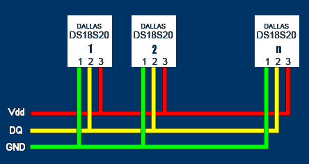
 
1wirebus.gif

 
I'm doing this today by twisting the in/out/sensor wires together and then soldering the joint for reliability and then covering with heat shrink. (Guess I could use wire nuts, but never had good experiences with thin cables.) 
 
This method works, but it's a pain if I want to add, replace or move a sensor.
 
What I'd like to do is to connect the incoming and outgoing wires from the bus to an RJ45 socket and then simply plug in the sensor (RJ45 connected to stub wires). (All sockets will be populated.)
 
Wondering if there's an easy way to do this
 
Regards
 
Mark 
 
 
Terminal blocks are another option.  The kind with a hold-down screw on the top and a point to insert the wire from the sides.
 
@Mark,
 
Here I just ran extra patched down catXX cable and repurposed it for 1-wire temp / humidity sensors.
 
I do have temperature and temperature / humidity sensors in every room of the house (including attic and basement).  (more than the Leviton / HAI temperature / humidity sensors in place today).
 
I do have catxx patch panels only used today for 1-wire sensors.  My outdoor lightning sensor wiring is different.
 
I have one 1-wire network still up today using only two wires of the 8 wires in a parasitic manner and it works just fine.
 
The advantage of parasitic powering is that it means you can have a two wire MicroLan. ("MicroLan" is just Dallas's trademarked name for a bunch of 1-Wire chips "playing nicely" with each other and a "master" device, e.g. a PC or simple microcontroller, e.g. Arduino, in charge of the network of 1-Wire sensors, actuators, storage units, etc.) If you don't use parasitic powering, then you need to run three wires from chip to chip to chip. (An aside: You should be aware that MicroLans don't like star topographies. If you need a star, you need a hub to split it into separate, non- star, legs.)
 
One way I have seen to do this is to connect the temperature sensor right to the RJ-45 jack making a tiny sensor.  The ones pictured are nice but too big.  You do not notice the ones with the sensors directly wired to the RJ45 jack. 
 
My set up is old and done in a star fashion topology which is not the methodology utilized today.
 
Note here have: 3 Temp-8 serial devices, a couple of Maxim USB 1-wire devices and a few of the Maxim serial 1-wire devices making up about a few autonmous 1-wire networks all coming together at the patch panel.  It is much easier to do these days with a 1-wire hub.  The combo humidity / temperature sensors need 3 wires.  These are a bit less than the Leviton / HAI combo sensors and a bit smaller.   I do have in place first generation ones that are parasitic / 15 years old and work just fine today.  These are tiny at about 1/3" in diameter using some miniature Maxim 1-wire chips. I have not seen any like this in a few years now.
 
The cables / temperature sensors you have shown also work but are not really easy to hide in a room.
 
You cannot do this with combination temperature and humidity sensors such that I went with just gluing these on to a simple RG-6 one hole cover plate. 
 
You can purchase the DS1820 series of temperature chips for pennies these days.
 
Have a look here for some interesting reading.
 
1-wire - one way to do it.


FN78GMDFBVHEEOE.MEDIUM.jpg
 
I haven't used 1-Wire but assuming the concepts of the databus are still the same - as I understand you have two leads that must be connected - an in/out - but of course you won't get 2 wires into a single spot on an RJ45 plug... however, since there are 8 terminals and only 6 wires in play here, it seems you could get the right result by having the IN 3 on one side of the RJ45 plug and the OUT on the other side - then make the connection between the two on the jack that they're plugged into on the back side.
 
Actually rereading your post - you want the sensor on the plug side and the bus on the jack side... if you were to run a single wire end to end and just "tap" in jacks, that would be easy - just carefully strip a section of the Cat5 and use the non-cutting blade to punch it onto the RJ45 jack - then let it loop back out to the next jack without ever cutting the wire.  If they're separate runs, then use a longer piece to pass through the jack - again without cutting the excess off, then scotch-lock to the next wire with the remaining stub.
 
Here is a 1-wire splat picture which shows the use of a 1-wire temperature sensor, RJ-45, parasitic or non parasitic circuit.
 
picture.jpg
 
Personally I still like the use of a parasitic network for just temperature sensors.  I have one of these in place today.  Rest are non parasitic.
 
I use non parasitic combo temperature / humidity sensors.  These are two types with two different supply voltages.
 
There is no defined standard relating to what wire is on what pin for an 8 wire category XX cable.
 
Only thing is that you have to keep track of the pinouts which really is no big deal unless you consider that difficult.
 
This is my favorite guide. 
 
1-Wire application Guide
 
Thanks for the thoughts guys. I like the idea of stripping the insulation and punching down the uncut wire. Only problem I have with that is that the the punchdown tool has a cutter. Have seen some cheap plastic ones that don't. Will see if I can find one
 
Regards
 
Mark
 
Mark - some of the cheaper punchdowns have the 66-block end on one side and the 110-block side on the other and you flip them - but the better ones have totally separate blades for 66 and 110 - and each one has a cutting and a non-cutting side so you just flip the blade over to not cut.  The other style blade is stored inside the handle.
 
punchdownblades.jpg
 
Here's one of the ones in my bag - a Fluke; This is one of my backups.  You can also often get the blade separate that's compatible if you already have a punchdown tool - like this one.  They're generally cross-compatible.
 
The punch down tool that I use has an end blade on it which I can adjust or change.  That said the 1-wire patch panels here are separate and located adjacent to the 1-wire controllers or whatever means I am using to get the data. 
 
I have gone to custom terminations mostly one the temperature / humidity side of the sensors relating to what wires to use.  That and initially just putting in a star topology then a hub and spoke methodology left me with much extra catxx cable. 
 
While the concepts of topology are easy and make sense the issues that I had was relating to the different voltages that I needed to utilize for the three types of combination temperature / humidity sensors and other 1-wire devices. 
 
IE: the original tiny combination sensors were purely parasitic (and still work today).  There is some magic involved in seeing the devices on the 1-wire bus.  That is where the hub and spoke methodology is supposed to fix some of this stuff versus the use of the star topology. 
 
Work2Play said:
Mark - some of the cheaper punchdowns have the 66-block end on one side and the 110-block side on the other and you flip them - but the better ones have totally separate blades for 66 and 110 - and each one has a cutting and a non-cutting side so you just flip the blade over to not cut.  The other style blade is stored inside the handle.
 
attachicon.gif
punchdownblades.jpg
 
Here's one of the ones in my bag - a Fluke; This is one of my backups.  You can also often get the blade separate that's compatible if you already have a punchdown tool - like this one.  They're generally cross-compatible.
 
Thanks!
 
pete_c said:
The punch down tool that I use has an end blade on it which I can adjust or change.  That said the 1-wire patch panels here are separate and located adjacent to the 1-wire controllers or whatever means I am using to get the data. 
 
I have gone to custom terminations mostly one the temperature / humidity side of the sensors relating to what wires to use.  That and initially just putting in a star topology then a hub and spoke methodology left me with much extra catxx cable. 
 
While the concepts of topology are easy and make sense the issues that I had was relating to the different voltages that I needed to utilize for the three types of combination temperature / humidity sensors and other 1-wire devices. 
 
IE: the original tiny combination sensors were purely parasitic (and still work today).  There is some magic involved in seeing the devices on the 1-wire bus.  That is where the hub and spoke methodology is supposed to fix some of this stuff versus the use of the star topology. 
 
Thanks Pete
 
Mark_anderson_us said:
Thanks for the thoughts guys. I like the idea of stripping the insulation and punching down the uncut wire.
Just to be clear, you would strip the cat5 cable sheath and punch down the insulated wire.
 
And as a side note, if you end up doing a lot of punch down connections consider getting the tool that DOES NOT have the spare blade kept in the handle.  The way the tab protrudes ends up being rough on the palm when you're punching down a lot of times in a row.  I had that kind and it's uncomfortable to use for more than a few punches in a row.
 
These guys appear to follow the pinout standard that seems to have evolved.
 

Code:
http://www.sheepwalkelectronics.co.uk/
 
Back
Top