apostolakisl
Senior Member
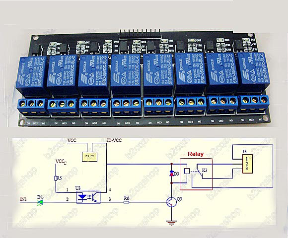
I purchased a relay board on ebay to use with my CAI. Of course, it came from china without a lick of documentation and no responses to emails.
The CAI outputs 8 TTL signals that can drive solid state relays, but these are coils. So, I need a separate power source to operate the relays. The relay board has a VCC contact which is where that power source goes. Question I have is the unit only has one ground (there are 2 contacts but they are connected on the pcb). Is it OK to share the ground from the CAI outputs with a ground from a separate power supply? And do you think a 9v power supply would be ok?
Also, there are three pins to the right. Gnd, VCC, JD-VCC. What the heck is JD-VCC? The unit arrived with a jumper connecting VCC with JD-VCC.


Thanks.