You are using an out of date browser. It may not display this or other websites correctly.
You should upgrade or use an alternative browser.
You should upgrade or use an alternative browser.
M1 installation
- Thread starter BB22
- Start date
Ok so I tried connecting only one wire to the wire tracer. I get multiple signals meaning from different wires. The signal is showing to have distortion meaning not clear. Can that be because wires are running side by side at some point in the wall?
The keypad next to the main door as one wire that goes to the door and a CAT5 but not sure where that goes. I also get a faded signal when I touch the CAT5 but the toner is connected to a different wire not a CAT 5. Does this make any sense?
The keypad next to the main door as one wire that goes to the door and a CAT5 but not sure where that goes. I also get a faded signal when I touch the CAT5 but the toner is connected to a different wire not a CAT 5. Does this make any sense?
There is another way to trace a pair of wires if you can access both ends of the cable.
Twist two wires together on one end of a cable. For instance you might twist the blue wire and blue/white wire of an ethernet cable together. Then go around the house putting an ohm meter or continuity tester on all of the same color pairs around the house. When you find the correct pair the meter will show that the pair is twisted together on it's far end.
Mike.
I've found the Fluke toner to put a pretty good strong signal on the wires. I've traced cat5e wire using twisted pairs for thirty feet anyways. The Fluke 300 toner is advertised to send a signal for ten miles.RAL said:If the cable is twisted pair, the twists cause the signal to cancel out. Instead of connecting the tone generator to both wires in the pair, connect it to just one of the wires and connect the other lead of the generator to ground. Sometimes, just letting the second lead from the generator dangle in the air works, too.
Also, the wires you are trying to trace should not be connected to anything at either end. If you were trying to trace a cable that's connected to a door or window contact, and the contact is closed, it's shorting out the two wires and that'll pretty much kill the signal.
Mike.
Pitbull50 said:Ok so I tried connecting only one wire to the wire tracer. I get multiple signals meaning from different wires. The signal is showing to have distortion meaning not clear. Can that be because wires are running side by side at some point in the wall?
Do you have direct access to the wires or are they behind a wall? If they are run alongside each other in a bundle it can be a little difficult to determine the cable that has the tone on it but it can be done by touching the tip of the probe to each cable, the cable with the signal should be noticeably louder than the others.
The wire between the keypad and the door was probably meant to control an electronic door striker. The cat5 at the keypad almost certainly goes back to the panel location eventually. I say eventually because it may go to other keypads or other bus devices on it's way back.Pitbull50 said:The keypad next to the main door as one wire that goes to the door and a CAT5 but not sure where that goes. I also get a faded signal when I touch the CAT5 but the toner is connected to a different wire not a CAT 5. Does this make any sense?
Mike.
If the house was only wired for an alarm, then the low voltage contractor would run the wires and connect them to say sensors for doors and windows. Motion, keypads, etc. are all run and then just left either behind the drywall, the attic, crawlspace, etc. My house was built and they put a panel in, they ran wires for four keypads by default but only put in a single keypad. The wires for the other three keypads are in the wall but they did at least bring them into the panel location.
So your lack of wiring probably means the wiring is not at the panel, but either behind it or in the attic. So have you actually gone into the attic to look for the wiring, you should be able to see it.
So your lack of wiring probably means the wiring is not at the panel, but either behind it or in the attic. So have you actually gone into the attic to look for the wiring, you should be able to see it.
Does this make sense?
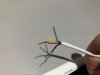
The picture with the two wires is where the keypad goes next to the door. The white wire connects to the door - was able to confirm with the wire tracer.
The yellow wire, I get a faded signal to the wire from the other picture. Thats the wire thats coming out from the 2nd keypad location. The signal is faded but I get some detection.
Could this be?
Thanks
Attachments

Pitbull50 said:Does this make sense?
The picture with the two wires is where the keypad goes next to the door. The white wire connects to the door - was able to confirm with the wire tracer.
The yellow wire, I get a faded signal to the wire from the other picture. Thats the wire thats coming out from the 2nd keypad location. The signal is faded but I get some detection.
Could this be?
Thanks
I would say no. Most keypads don't need four pairs. Most likely, they ran a cable for a phone line. You need to go into the attic and look to see what cables you can see.
BraveSirRobbin
Moderator
You can get some 'bleed through' if the wires are close together. Also, are both ends of the wires free from any panel or sensor?
You can confirm the wire by checking the continuity. From my (dated) How-To Install a Home Security System Post:
You can confirm the wire by checking the continuity. From my (dated) How-To Install a Home Security System Post:
Basically you connect to whatever you are tracing (in this case it would be the flying leads of say a window. Turn the base unit on, then take the inductive "wand" and trace over the bundle of cables in your homerun location. The closer you get to the correct one the louder the buzzing signal from the wand will be, until you quickly find the correct cable.
Once the wiring is labeled you will want to do two checks, both which will require a multimeter to measure resistance. First strip back the wiring insulation on all the wiring leads. Make sure that the cable you are going to test has no leads touching each other on either end of the cable. Then set your multimeter on the highest resistance scale possible (if your meter "autoscales" skip this step). Then measure between each cable in its own bundle (for instance in the bundle with only a single pair, you would measure between those two wires. In a two pair bundle you would measure between each possible combination of wires in that bundle.
You want to make sure that the meter reads "infinite" or the same as when you have nothing connected to the meter's leads. This will insure that no short exists between wires in a bundle.
Next you want to insure there is "continuity" between each cable. The easiest way to do this is to use a small wire jumper clip and clip between each lead to say a common lead in the bundle. For instance if you have a yellow, green, black, and red color wires in a bundle, put the first clip on the black then the other clip on the red. Then go to the other end of the cable and measure between the black and red wire with your meter on the lowest resistance setting possible (again, the autoscale comment). You want to see a near zero reading. The reading will not be exactly zero because there is a few ohms resistance in the wire itself. A reading over five ohms though, would be an item of concern unless the cable is extremely long (I'm guessing over 500 feet).
This step will take up some time, but it could save you a lot of frustration when trying to make all the other items work.