Monitoring voltages

To determine accuracy the DS2438 is a 10-Bit Analog to Digital converter. If you looked at the Analog to Digital Converter Guide you would see ten bits is "2 to the 10th" power or 1024. This means the "measured" voltage (ten volts max) has a bit accuracy of 10/1024 or .01 volts.

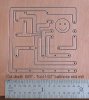
Let's not confuse resolution with accuracy! The resolution of the DS2438 is indeed 10mV (0.01V). The accuracy of the ADC is given as +/-75mV over the input range of 1.5 to 10.0V on the VAD input (per the spec sheet). NOTE: the circuit in the diagram uses the VDD input to measure the battery voltage. The VDD input accuracy is greater than the VAD input (50mV instead of 75mV but has a lower bottom threshold - 2.4V instead of 1.5).

Your accuracy is also affected by the tolerance of the resistors chosen. 1% resistors are extremely common these days, so they should not induce much of an error and, if chosen carefully, can have no effect on the accuracy.

Regardless of all this, the OP was looking for 0.1V accuracy, so the DS2438 is a reasonable fit for this.

Mitch
 
Thanks Robin, I came up with 10K and 14K for R5 and R6 also.

I came up with a minimum of around 103 ohms for R7.

The only component that confuses me is R1 at .05 ohms?
It looks like they have drawn it as a pot set up as a variable resistor.

I am only interested in reading the voltage on two large 12V deep cycle marine batteries set up in series.
I don't need to read any current so I am not sure I need worry about R1?

I sell 1% tolerance metal films and all the other parts listed except the zener diodes.
Just have to pick up a couple DS2438's from Eric

I'll pick up one of snazzy USB one wire hubs for another experiment.
 

Attachments

  • DS24382.gif
    DS24382.gif
    28.8 KB · Views: 41
R1 is used to measure the charging current, so if you don't need to do that, just connect the BAT- to ground (PAC-) and leave out R1.

Mitch
 
Charge current to the battery would be an interesting parameter to measure, especially if more than one solar panel is used.

I would also measure the voltage from each battery if possible.

Graphing the results can also tell you a lot about the panels performance, especially when compared to the solar data.

You will see subtle changes and could diagnose problems before they become major. For instance I graph battery voltages (12 volt single battery system) on various solar charged panels (for work). As you can see in the graph below the "ASP" voltages for Site 6 are less then Sites 3 and 8 (identical current draws). The battery is old and had a pretty good load on it before it was able to charge, and would never be able to regain its "full" charged voltage. I have read this can occur on certain batteries if they are drawn down to under 50% of their capacity. Over the course of four days you could see the small decrease in the waveform's peak voltage.

Also, you can see in the ASP voltages that those panels are slightly undersized for the load. Thus their graphs don't have the sharp increase in voltage as their "SYSTEM" counterpart's graphs. This helped me size newer correct solar panels (which I started a thread on here), plus other peripherals including charge controllers and battery types.

Anyway this is probably more than you wanted to know, but I'm just now learning about solar charged systems myself (so this is on the top of my mind right now).

I would be curious and interested in other people's experience with solar charged systems (I'm certainly no expert and woud like to hear various opinions). Lets reply to THIS thread though for posts concerning this subject so we don't cloud Eric's forums with off-topic posts! :(
 

Attachments

  • stationbat.jpg
    stationbat.jpg
    79.6 KB · Views: 42
I am gonna be using a solar charge controller which handles all the charging and and monitors the loads.
I ordered a small 10 amp model, should be here next week.

They will cut off the load at a certain voltage so the batteries do not get damaged.
They also control the charging and will go into trickle charge mode to keep from over charging.
Some charge controllers can read the battery temps with a sensor and set the charging accordingly so you don't over cook them.

Here's some info on charge controllers, pretty cool devices.
http://www.morningstarcorp.com/products/Su...S_DataSheet.pdf


I am more interested in collecting battery voltages and voltages coming off the solar panel in relation to sun strength.
I have one of the HB solar sensors.

I'll have all the data collected from my one wire sensors on real time graphs, just for my own entertainment and to see the relation between the sun strength and voltage output at different times of the year.
 
I ordered a few DS2438 chips from Eric and then designed a PC board for the circuit shown in this post above.

I then cut the board on my CNC machine, which was a challenge, being that the DS2438 is a SOIC surface mount device, and very tiny.

I set up a web page documenrting the CNC process in case anyone likes that sort of thing.
http://www.el34world.com/Misc/Cnc/CNC14.htm

I'll post another picture when I get the board loaded with parts and working.
 

Attachments

  • board1.jpg
    board1.jpg
    36.3 KB · Views: 35
I'm using vis * 11.5 + 0.6 which I calibrated manually with digital meter. Seems to be accurate to 1/10 VDC.


I just got a 24volt solar panel.
I want to monitor the DC voltage coming off the panel.
I'll use my HB solar sensor also so I can get a graph with solar readings and solar panel output readings.

I was looking at your store Eric, looks like the HVAC Monitor would be what I want to monitor the solar panel/battery system?

The HVAC Monitor was designed to monitor whether a voltage is present or absent but you can read the actual voltage using the formula VOUT = (VIN - 0.7) /10. I would not use it for precision measurements but to get a close idea of the voltage it would work OK.

Eric
 
Ah yes, thanks, that confirms my thinking on that doc sheet.
Appreciate the info.

What kind of accuracy would you guess can be obtained setting that circuit up for 24volts DC measurment?

The AN125 doc sheet seems to indicate that you can get fairly accurate, but does not give any figures?

For higher accuracy measurements, each unit can be individually calibrated with a precision voltage reference and the multiplier data stored inside the DS2438's user EEPROM.

I'b be happy with 1/10 volt :eek:

EDIT:
Just curious if you used the circuit shown below for your 12 volt system and if so what values did you end up using for R5, R6 and R7 ?

DS24382.gif
You probably already know this, but for others, If you use the DS2438 circuit shown it needs at least 7 or 8 volts from the solar panel or it won't
operate properly. (dependent on R7) If your charging a battery with the solar panel, maybe get the Vdd from the battery and monitor the solar panel
at the Vad input. I think the panel and battery would be diode isolated.
Mike
 
I'm surprised that Mitch from Midon hasn't mentioned that Midon now has a 1wire circuit board (named: 1WSwitch http://www.midondesign.com/1WSwitch/1WSwitch.html) that can be used to measure voltages from 0 to 5VDC. I have been using it to measure the output from a single solar cell. I am collecting the data to see if I can predict what the output of a solar panel might be when I mount it on the roof. Attached is a typical graph.

With the addition of a couple of resistors, the range could be easily adjusted.

For now, I am using the solar cell to tell my home automation system if the sun is shining brightly at 1 hour after sunrise. If it is, it turns off the power to my security camera to prevent damage from the sun shining into the lens.

Steve Q
 

Attachments

  • Solar_Cell.jpg
    Solar_Cell.jpg
    14.4 KB · Views: 32
Back
Top