Hi Ross and CAI Support,
Thanks for the advice regarding this. Sorry I wasn't clear on the pH probe matter. The confusion may have been the phidget boards I was using, but want to eliminate and so that I can connect the probes directly to the webamp.
I'm not sure I would be skilled enough to replace an SO package chip. And given that you said "clean them really well and keep them dry" it seems like a tricky task. I do have a fine tipped soldering iron and would be willing to give it a go. Maybe I could send one of the boards back and get you send one with the LMP7704 or MCP6004? Of course I would pay for postage (to and from NZ).
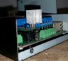
Also, were you aware that with the regulator installed on the webamp board it does not fit in the standard CAI enclosure?
I don't want to thread hijack as this subtopic seems to be occupying a few posts now. Should we start a new thread in this section?
Marty
Thanks for the advice regarding this. Sorry I wasn't clear on the pH probe matter. The confusion may have been the phidget boards I was using, but want to eliminate and so that I can connect the probes directly to the webamp.
I'm not sure I would be skilled enough to replace an SO package chip. And given that you said "clean them really well and keep them dry" it seems like a tricky task. I do have a fine tipped soldering iron and would be willing to give it a go. Maybe I could send one of the boards back and get you send one with the LMP7704 or MCP6004? Of course I would pay for postage (to and from NZ).
Also, were you aware that with the regulator installed on the webamp board it does not fit in the standard CAI enclosure?
I don't want to thread hijack as this subtopic seems to be occupying a few posts now. Should we start a new thread in this section?
Marty