I’m just trying to establish a set up so I don’t have anything but the TED equipment. While I was researching I ran across this post on github, https://github.com/resynthesize/ted. Do you know if this is the basic file set up that’s needed? I'm looking set run something like this on a full PC. I have an UNRAID box and in the process of standing up a pfsense box.
You are using an out of date browser. It may not display this or other websites correctly.
You should upgrade or use an alternative browser.
You should upgrade or use an alternative browser.
Very Cheap TED 1001 House Power Monitors (and possible hacking)
- Thread starter naething
- Start date
XRinger
Member
The first TED 1001 sytem that I got many years ago, came with software and the USB port was actvie. (I used the FootPrints program).
These new Ebay-dump TEDs look like the same unit, but their USB ports don't do anything. They are not active. (IIRC).
I think that software at your link, might be for the older USB enabled unit.. So, the cheap Ebay models won't work with those programs.
Because of the lack of the USB I/O..
These new Ebay-dump TEDs look like the same unit, but their USB ports don't do anything. They are not active. (IIRC).
I think that software at your link, might be for the older USB enabled unit.. So, the cheap Ebay models won't work with those programs.
Because of the lack of the USB I/O..
The unit that I have an older model also. In the begining I used the footprints software but I’ve been through so many PCs over the years its long gone. That said I think I prefer the Linux box method as it doesn't bog down my windows machine like before. Also my primary PC is running Win 10. I checked the unit I have and per the TED web site it's the unlocked version.
“To determine whether or not your system is 'locked' or 'unlocked', unplug the Display from the wall. Wait 15 seconds and plug it back in. For 5 seconds, there will be a number in the lower-right that ends in either an "L" (Locked) or a "U" (Unlocked) “.
Which I take it as it came with the software. I possibly could get them to send me a copy if I asked. I have seen posts on other sites that lead me to think that the newer units don't just stream the data they require a polling message first.
You mentioned a circuit diagram earlier. I found a post that talks about a homemade/DIY receiver. http://scanlime.org/2008/10/interfacing-with-the-energy-detective/. They seem to have done an awesome job of making a circuit that filters and amplifies to get the RAW digital signal direct from the power line. Its says the latest schematics and firmware to the box they made are here http://svn.navi.cx/misc/trunk/tedrx/. Its a bit deeper that i want to go right now. I’m hoping to get my data direct from the 1001 either from the USB or modify it and get the RAW data direct from it.
XRinger
Member
People are still messing around with the "L" Ebay models.. http://www.mtspencer.com/2014/08/10/energy-monitor/
I should be able to solve my problem by adding a cap to one of my transmitters, to shift into into a faster or slower clock rate,
so that the synced-up time window will be shorter. If I can get it lock-up down to a couple of minutes, I'll be happy..
I should be able to solve my problem by adding a cap to one of my transmitters, to shift into into a faster or slower clock rate,
so that the synced-up time window will be shorter. If I can get it lock-up down to a couple of minutes, I'll be happy..
hi there have not being here for a while, was wondering if anyone could help me witha little programing problem--
i first hacked the ted 1001 reciever, and it working great still, but now i hacked the the MTU which was surprisingly simple it basically the same as the reciever but only instead of tapping into TX you tap into the RX. and i want to connect an ardino directly to the MTU. I can pull of the hex data transmitted from MTU with out problem ( you can connect a standard FT232RL usb serial to it and connect to the computer and use the original perl scripts posted on this page)
but now I want to connect an ARDUINO directly to it. basically all you need is a ground wire and a wire attched to pin one of TDA5051A chip gnd to the arduino grd and pin 1 to the RX on the ardoino
here a simple sketch that will display the hex coming from the MTU
void setup() {
Serial.begin(1200);
}
void loop() {
{
if (Serial.available() > 0) {
int INFILE = Serial.read();
Serial.print("received: ");
Serial.println(INFILE, HEX);
}
}
}
but i can not figure out how to get this section of perl code used to process the incoming data into a usabale form as C does not have the same commands as perl does.. was wondering if anyone would be kind enough to translate this section of code from Perl code into C that would be compatible with an arduino..
system("stty -F /dev/ttyUSB0 1200 cs8 raw");
open INFILE, "/dev/ttyUSB0"
or die "\nCannot open /dev/ttyUSB0!\n";
# this top part for the arduino is handled by the pevious post sketch,
# but i can not figure out what to do for the rest, as perl has alot of commands
# that do not exist in C so I am lost what to do for alot of it,,
@data = (); # do not know what to do for this argument or pretty much most of what below
$buf = "";
$started = 0;
sub processPacket($);
while (read(INFILE, $buf, 1)) {
$d = ord($buf) ^ 0xff;
if ($d == 0x55 && $started == 0) {
$started = 1;
$a = 0;
}
if ($started == 1) {
$data[$a] = $d;
$sum += $data[$a];
$a++;
if ($a >= 11) {
$sum -= $data[9];
$sum &= 0xff;
if ($sum == 0) { processPacket($data); }
$started=1;
$a = 0;
}
}
}
# Working sub process packet stuff
sub processPacket($) {
local($data) = @_;
# If the power reading is way off, uncomment the other power line
$power = (($data[5]^0xff)<<8) + ($data[4]^0xff);
# $power = ($data[5]<<8) + $data[4];
$voltage = ($data[8] << 8) | $data[7];
$voltage = sprintf("%.3f",123.6 + ($voltage - 27620) / 85 * 0.2);
$power = sprintf("%.3f",(1.19 + 0.84 * (($power - 288.0) / 204.0)));
print " KW $power, Voltage $voltage\n";
any help would be appreciated.
thank you for your time and effort
hi there does anyone know what might be wrong with this arduino code by some chance
I hacked the MTU of the ted 1001 and connected it directly to an arduino
but something goes wrong in the the math format
here is a debug perl test file with a know data -
#!/usr/bin/perl -w -s
{
$test1 = 0x47;
$test2 = 0xFF;
$test3 = 0x03;
$test4 = 0x69;
print "\n";
print "$test1,$test2,$test3,$test4\n";
$power = ($test2<<8) + $test1;
$voltage = ($test4<<8) |$test3 ;
print "$power,$voltage\n";
$voltage = 123.6 + ($voltage - 27620) / 85 * 0.4;
$power = 1.19 + 0.84 * (($power - 288.0) / 204.0);
print "$power,$voltage\n";
}
it gives a proper output of --
71,255,3,105
65351,26883
269.096470588235,120.131764705882
but the arduino give nothing close for the same data
void setup() {
// put your setup code here, to run once:
Serial.begin(1200);
Serial.println("<Arduino is ready>");
byte j = 0x03;
byte k = 0x69;
byte r = 0xFF;
byte m = 0x47;
byte voltage = 0;
byte power = 0;
voltage = ( k<< 8) | j;
Serial.print("voltage prequ ");
Serial.println(voltage);
//byte volt = voltage;
//Serial.println(volt);
voltage= (123.6 + (voltage - 27620) / 85 * 0.2);
Serial.print("voltage ");
Serial.println(voltage);
// Serial.println (" ");
power = (r<<8) + m;
Serial.print("Power prequ ");
Serial.println(power);
//volt = voltage;
power = 1.19 + 0.84 * ((power - 288.0) / 204.0);
Serial.print("power out ");
Serial.println(power);
}
void loop() {
}
<Arduino is ready>
voltage prequ 25 -------->should output this instead 26883
voltage 58 ------------------> 120.131764705882
Power prequ 255 --------> should be this instead 65351
power out 1 --------------->269.096470588235
any one have any ideas -- ? ? ? ?
Well, the most obvious problem is that your scalar variables are under sized. The byte scalars can only hold a value between 0 and 255 on most computer architectures since they are only 8 bits in size. The values you are computing are too large to store in a byte variable. Thus, it creates an overflow condition causing the variable to wrap.
I'm not that familiar with the Arduino architecture, but you need a 16 bit scalar for all your variables.
Here's a basic example compiled on a Windows 10 desktop
#include <stdio.h>
int main(int argc, char* argv[])
{
unsigned int j = 0x03;
unsigned int k = 0x69;
unsigned int r = 0xFF;
unsigned int m = 0x47;
unsigned int power = 0;
power = (r << 8);
power += m;
power = 1.19 + 0.84 * ((power - 288.0) / 204.0);
printf("power = %d\n", power);
return 0;
}
EDIT
Change your byte data type to int data type and your problem should be resolved.

if you want a basic copy of the arduino code here it is it is a bit messy as it was my debuging code, i accidentally forgot to save the one with the LCD attached i have to rewrite it again tomorrow.
// adapted from Serial Input Basics
// char data type replaced by byte
const byte numBytes = 32;
byte receivedBytes[numBytes];
byte numReceived = 0;
int cnt = 0;
boolean newData = false;
void setup() {
Serial.begin(1200);
Serial.println("<Arduino is ready>");
Serial.begin(1200);
}
void loop() {
recvBytesWithStartEndMarkers();
showNewData();
}
void recvBytesWithStartEndMarkers() {
static boolean recvInProgress = false;
static byte ndx = 0;
byte startMarker = 0xAA;
byte endMarker = 0xAA;
byte rb;
while (Serial.available() > 0 && newData == false) {
rb = Serial.read();
if (recvInProgress == true) {
if (rb != endMarker) {
receivedBytes[ndx] = rb;
ndx++;
if (ndx >= numBytes) {
ndx = numBytes - 1;
cnt++;
}
}
else {
receivedBytes[ndx] = '\0'; // terminate the string
recvInProgress = false;
numReceived = ndx; // save the number for use when printing
ndx = 0;
newData = true;
}
}
else if (rb == startMarker) {
recvInProgress = true;
}
}
}
void showNewData() {
if (newData == true) {
Serial.print("This just in ... ");
for (byte n = 0; n < numReceived; n++) {
Serial.print(receivedBytes[n], HEX);
Serial.print(' ');
}
Serial.println();
showGroupsOfBytes();
newData = false;
}
}
void showGroupsOfBytes() {
if ( receivedBytes[0]==0x4E ) {
// if (numReceived < 9) {
byte j = 0;
byte k = 0;
byte m = 0;
byte r = 0;
byte h = 0x4E;
byte n = (0);
//n < numReceived; ) {
h = receivedBytes[0];
h = ~h;
// Serial.print("MTU ");
// Serial.println(h, HEX);
// Serial.print(' ');
// Serial.println ("Voltage");
j = receivedBytes[6] ;
k = receivedBytes[7];
// Serial.print("hex pre invert ");
// Serial.print(j, HEX);
// Serial.print(" ");
// Serial.println(k, HEX);
j= ~j;
k= ~k;
// Serial.print("hex inverted ");
// Serial.print(j, HEX);
// Serial.print(" ");
// Serial.println(k, HEX);
//Serial.print("Dec ");
//Serial.print(j);
// Serial.print(" ");
//Serial.println(k);
double voltage = 0;
double power = 0;
voltage = ( k<< 8) | j;
//Serial.print("voltage prequ ");
// Serial.println(voltage);
//byte volt = voltage;
//Serial.println(volt);
voltage= (123.6 + (voltage - 27620) / 85 * 0.4);
Serial.print("voltage ");
Serial.println(voltage);
// Serial.println (" ");
// Serial.println ("Power");
m = receivedBytes[3] ;
r = receivedBytes[4];
/* Serial.print("hex pre invert ");
Serial.print(m, HEX);
Serial.print(" ");
Serial.println(r, HEX);
*/
m= ~m;
r= ~r;
/* Serial.print("hex inverted ");
Serial.print(m, HEX);
Serial.print(" ");
Serial.println(r, HEX);
Serial.print("Dec ");
Serial.print(m);
Serial.print(" ");
Serial.println(r);
*/
power = (r<<8) + m;
// Serial.print("Power prequ ");
// Serial.println(power);
//volt = voltage;
power = 1.19 + 0.84 * ((power - 288) / 204);
Serial.print("power out KW ");
Serial.println(power);
// }
// }
Serial.println();
cnt = 0;
}
// }
}
now I just have to finish up my bit of code and combine them together into one. as my main purpose of hacking the MTU was so that I could monitor the whole building energy consumption and build a GTI limiter, and when my solar panels out put more then i need it will throttle them back automatically , the modular boards I built can handle up to 12 different modules and each module depending on the amperage should be able to do 1.5 kw . as the one I use are 50v at 20amp.. but it easily scale to 90v at 60amp. actually all i waiting for is a couple resistors to come in and the prototype would be done ..
oh yeah you should probably delete or change this to match your MTU i was just using as a way to discard bad sets
if ( receivedBytes[0]==0x4E ) {
^
not sure if it posting as I try a a capta pops up and nothing happens so hopefully I do not post this multiple times
Hi bob I tried what you suggested but it did not work same bad data. but double works fine, even though it rounded abit to two decimal place
here a cleaned up code for anyone who wants it includes I2C LCD
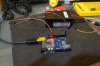
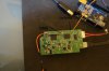
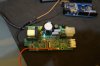
it actually works nicer then the TED as it displays what direction the Current is going +/- I will prepare a couple pictures where to add the wire to the MTU and post them
#include <stdio.h>
#include <Wire.h>
#include <LiquidCrystal_I2C.h>
// Set the LCD address to 0x27 for a 16 chars and 2 line display
LiquidCrystal_I2C lcd(0x27, 16, 2);
const byte numBytes = 32;
byte receivedBytes[numBytes];
byte numReceived = 0;
int cnt = 0;
boolean newData = false;
void setup() {
Serial.begin(1200);
Serial.println("<Arduino is ready>");
// Serial.begin(1200);
lcd.begin();
}
void loop() {
recvBytesWithStartEndMarkers();
showNewData();
}
void recvBytesWithStartEndMarkers() {
static boolean recvInProgress = false;
static byte ndx = 0;
byte startMarker = 0xAA;
byte endMarker = 0xAA;
byte rb;
while (Serial.available() > 0 && newData == false) {
rb = Serial.read();
if (recvInProgress == true) {
if (rb != endMarker) {
receivedBytes[ndx] = rb;
ndx++;
cnt++;
if (ndx >= numBytes) {
ndx = numBytes - 1;
}
}
else {
receivedBytes[ndx] = '\0'; // terminate the string
recvInProgress = false;
numReceived = ndx; // save the number for use when printing
ndx = 0;
newData = true;
}
}
else if (rb == startMarker) {
recvInProgress = true;
}
}
}
void showNewData() {
if (newData == true) {
Serial.print("This just in ... ");
for (byte n = 0; n < numReceived; n++) {
Serial.print(receivedBytes[n], HEX);
Serial.print(' ');
}
Serial.println();
showGroupsOfBytes();
newData = false;
}
}
void showGroupsOfBytes() {
if ( receivedBytes[0]==0x4E ) {
// if (cnt == 9) {
byte j = ~receivedBytes[6];
byte k = ~receivedBytes[7];
byte m = ~receivedBytes[3];
byte r = ~receivedBytes[4];
double voltage = 0;
double power = 0;
voltage = ( k<< 8) | j;
voltage= (123.6 + (voltage - 27620) / 85 * 0.4);
// Serial.print("voltage ");
// Serial.println(voltage);
power = (r<<8) + m;
power = 1.19 + 0.84 * ((power - 288) / 204);
// Serial.print("power out KW ");
// printf("power out %.4f",power);
// Serial.println(power);
lcd.setCursor(0,0);
lcd.print("volts ");
lcd.print(voltage);
lcd.setCursor(1,1);
lcd.print("kw ");
lcd.print(power);
}
// Serial.println();
cnt = 0;
}
Hi bob I tried what you suggested but it did not work same bad data. but double works fine, even though it rounded abit to two decimal place
here a cleaned up code for anyone who wants it includes I2C LCD
it actually works nicer then the TED as it displays what direction the Current is going +/- I will prepare a couple pictures where to add the wire to the MTU and post them
#include <stdio.h>
#include <Wire.h>
#include <LiquidCrystal_I2C.h>
// Set the LCD address to 0x27 for a 16 chars and 2 line display
LiquidCrystal_I2C lcd(0x27, 16, 2);
const byte numBytes = 32;
byte receivedBytes[numBytes];
byte numReceived = 0;
int cnt = 0;
boolean newData = false;
void setup() {
Serial.begin(1200);
Serial.println("<Arduino is ready>");
// Serial.begin(1200);
lcd.begin();
}
void loop() {
recvBytesWithStartEndMarkers();
showNewData();
}
void recvBytesWithStartEndMarkers() {
static boolean recvInProgress = false;
static byte ndx = 0;
byte startMarker = 0xAA;
byte endMarker = 0xAA;
byte rb;
while (Serial.available() > 0 && newData == false) {
rb = Serial.read();
if (recvInProgress == true) {
if (rb != endMarker) {
receivedBytes[ndx] = rb;
ndx++;
cnt++;
if (ndx >= numBytes) {
ndx = numBytes - 1;
}
}
else {
receivedBytes[ndx] = '\0'; // terminate the string
recvInProgress = false;
numReceived = ndx; // save the number for use when printing
ndx = 0;
newData = true;
}
}
else if (rb == startMarker) {
recvInProgress = true;
}
}
}
void showNewData() {
if (newData == true) {
Serial.print("This just in ... ");
for (byte n = 0; n < numReceived; n++) {
Serial.print(receivedBytes[n], HEX);
Serial.print(' ');
}
Serial.println();
showGroupsOfBytes();
newData = false;
}
}
void showGroupsOfBytes() {
if ( receivedBytes[0]==0x4E ) {
// if (cnt == 9) {
byte j = ~receivedBytes[6];
byte k = ~receivedBytes[7];
byte m = ~receivedBytes[3];
byte r = ~receivedBytes[4];
double voltage = 0;
double power = 0;
voltage = ( k<< 8) | j;
voltage= (123.6 + (voltage - 27620) / 85 * 0.4);
// Serial.print("voltage ");
// Serial.println(voltage);
power = (r<<8) + m;
power = 1.19 + 0.84 * ((power - 288) / 204);
// Serial.print("power out KW ");
// printf("power out %.4f",power);
// Serial.println(power);
lcd.setCursor(0,0);
lcd.print("volts ");
lcd.print(voltage);
lcd.setCursor(1,1);
lcd.print("kw ");
lcd.print(power);
}
// Serial.println();
cnt = 0;
}
")
sorry here one more post I updated the code for better error correction, it first checks if the fist byte matches your MTU, then it checks if the number of bytes is correct ( 10), as the MTU throws out erroneous errors now and then
Code:
 #include <stdio.h>
#include <Wire.h>
#include <LiquidCrystal_I2C.h>

// Set the LCD address to 0x27 for a 16 chars and 2 line display
LiquidCrystal_I2C lcd(0x27, 16, 2);

const byte numBytes = 32;
byte receivedBytes[numBytes];
byte numReceived = 0;
int cnt = 0;

boolean newData = false;

void setup() {
    Serial.begin(1200);
    Serial.println("<Arduino is ready>");
   // Serial.begin(1200);
    lcd.begin();
}

void loop() {
    recvBytesWithStartEndMarkers();
    showNewData();
}

void recvBytesWithStartEndMarkers() {
    static boolean recvInProgress = false;
    static byte ndx = 0;
    byte startMarker = 0xAA;
    byte endMarker = 0xAA;
    byte rb;


    while (Serial.available() > 0 && newData == false) {
        rb = Serial.read();

        if (recvInProgress == true) {

            if (rb != endMarker) {
                receivedBytes[ndx] = rb;
                ndx++;
                cnt = ndx;
                if (ndx >= numBytes) {
                    ndx = numBytes - 1;


                }
            }
            else {
                receivedBytes[ndx] = '\0'; // terminate the string
                recvInProgress = false;
                numReceived = ndx;  // save the number for use when printing
                ndx = 0;
                newData = true;
            }
        }

        else if (rb == startMarker) {
            recvInProgress = true;

        }
    }
}

void showNewData() {
    if (newData == true) {
        Serial.print("This just in ... ");
        for (byte n = 0; n < numReceived; n++) {
            Serial.print(receivedBytes[n], HEX);
            Serial.print(' ');
        }
        Serial.println();
        showGroupsOfBytes();
        newData = false;

    }
}

void showGroupsOfBytes() {
    if ( receivedBytes[0]==0x4E )  {  // change this to match your MTU it - it will display in serial print
     if (cnt == 10) {
    byte j = ~receivedBytes[6];
    byte k = ~receivedBytes[7];
    byte m = ~receivedBytes[3];  // If the power reading is way off, remove/add " ~ "
    byte r = ~receivedBytes[4];  // If the power reading is way off, remove/add " ~ "


double voltage = 0;
double power = 0;

voltage = ( k<< 8) | j;
voltage= (123.6 + (voltage - 27620) / 85 * 0.4);
  // Serial.print("voltage ");
   //    Serial.println(voltage);


 power = (r<<8) + m;
 power = 1.19 + 0.84 * ((power - 288) / 204);

      // Serial.print("power out KW ");
     //  printf("power out %.4f",power);
      // Serial.println(power);
    lcd.clear();
    lcd.setCursor(0,0);
    lcd.print("volts ");
    lcd.print(voltage);
    lcd.setCursor(1,1);
    lcd.print("kw ");
    lcd.print(power);

       }
    }
    cnt = 0;

}Similar threads
- Replies
- 5
- Views
- 4K
- Replies
- 14
- Views
- 1K