Determining if Generator is running.

Big517

Active Member
Hello All,
 
I'm trying to monitor my GE Symphony II Generator to determine when it's ON or OFF.  
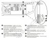
i've got an ELK with a zone already wired to the "Fault" output on the generator, however I would prefer to trigger simply when the generator is running.
I attached the wiring diagram.
Here is the link  page 25 shows the connections i'm assuming i'll need to use.  It's currently connected to the fault N/O contacts.
 
If anyone can advise how to monitor the status that would be great.  I should note that it does come with a wireless monitor which lights an LED up, however I do not want to rely on that, and prefer the hard-wire directly to the Generator.
 
Thank you


Attachments

  • Capture.JPG
    Capture.JPG
    100.6 KB · Views: 54
Many ways to do this.  IF you are concerned that the generator is indeed running and outputting an active voltage, I would get (optimmaly) a 240 volt AC coil relay and put it across the terminal outputs, then just monitor that contact closure.  Or, as you might have trouble finding that type of relay for cheap, the two 120 volt AC coiled relays, wire each between the L1 output and neutral, then the other to L2 output and neutral, then monitor those contact closures in a series wiring scheme.
 
If you wanted, and only wanted 'one' input, you could just wire all the contact closures from the relay in series with the fault sensor, but that means you would only get an overall "OK" signal if there were no faults as well (i.e. both legs outputting power PLUS no faults in the system).
 
Looked at your manual and BSR has it covered above.
 
1. Add relays
 
2. Assume that no fault means that it started and is running when expected.
 
Just shy of tapping in to the engine controls (Ignition circuit, etc.) these are your two options that will be the easiest.
 
Thank you for the quick responses.  Any suggestion on the relay to buy?  I noticed there is very large variation, and would be great if you could point me in the direction of the one you would suggest.
 
Thanks again!
 
I would stay away from the high voltage by using the LED connection.  Two approaches:
 
A) Use a low current relay to convert the LED drive to dry contact.  This is super simple, but you will need to mount the relay somewhere and protect it from the elements.
 
B) Install a suitably sized resistor in place of the LED.  The correct resistor will give you a zone voltage of about 7 volts which is the same as the secure state EOLR zone voltage when the generator is running.  I don't know the characteristics of the LED drive; otherwise, I'd calculate the resistor value for you.  You could use a variable resistor to find the voltage, just measure the resistance required, and get the nearest fixed value resistor from Radio Shack.  Please check the open circuit LED voltage to make sure this is a viable option.  You're looking for 8+ volts.
 
RIB's are used all the time for this, both industrially and commercially, in addition to HO level equipment.

Easy enough and cheap enough to do without messing with the LED's and attempting to drive a different relay. Also, not what I'd call reliable, especially if you consider the genset to be mission critical.
 
Then you need to determine what sort of monitoring you want to do...such as monitor an "exercise" session, a FTS, running, output, fault, etc.
 
IF this is a mission critical generator, I would want to ensure that the device meant to keep running is still functional (i.e. the transfer was handled correctly).  You can easily do this by monitoring the current of one or both legs (depending on how you have the generator's output wired up).
 
HERE is a recent thread where I recommended a variable 'threshold' current sensor that will give a contact closure after a set threshold of current is reached.
 
EDIT:  On second thought, why not monitor the critical device's current after the transfer switch, then you will know if that mission critical unit is on via the Elk even when not being supplied with the generator! ;)
 
jpmargis said:
I would stay away from the high voltage by using the LED connection.  Two approaches:
 
A) Use a low current relay to convert the LED drive to dry contact.  This is super simple, but you will need to mount the relay somewhere and protect it from the elements.
 
B) Install a suitably sized resistor in place of the LED.  The correct resistor will give you a zone voltage of about 7 volts which is the same as the secure state EOLR zone voltage when the generator is running.  I don't know the characteristics of the LED drive; otherwise, I'd calculate the resistor value for you.  You could use a variable resistor to find the voltage, just measure the resistance required, and get the nearest fixed value resistor from Radio Shack.  Please check the open circuit LED voltage to make sure this is a viable option.  You're looking for 8+ volts.
 
Perfectly reliable - mission critical or not!
 
jpmargis said:
I would stay away from the high voltage by using the LED connection.  Two approaches:
 
A) Use a low current relay to convert the LED drive to dry contact.  This is super simple, but you will need to mount the relay somewhere and protect it from the elements.
 
B) Install a suitably sized resistor in place of the LED.  The correct resistor will give you a zone voltage of about 7 volts which is the same as the secure state EOLR zone voltage when the generator is running.  I don't know the characteristics of the LED drive; otherwise, I'd calculate the resistor value for you.  You could use a variable resistor to find the voltage, just measure the resistance required, and get the nearest fixed value resistor from Radio Shack.  Please check the open circuit LED voltage to make sure this is a viable option.  You're looking for 8+ volts.
 
I don't own this particular GE generator, but I did read up on the hard wired status panel that connects to the LED output.   It appears that the LED signal is used to flash a code of 1 to 8 pulses to indicate various generator trouble conditions as follows:
 
1 Low Oil Shutdown
2 Engine Does Not Start
3 Low Frequency
4 Engine Overspeed
5 Low Voltage
6 Low Battery Voltage
7 Oil Temp High
8 Transfer Switch Fault
 
None of them indicate that everything is OK.  I don't think I'd want to depend on the lack of a flash code as proof that things are working and would much rather use the RIB relay.
 
My vote. RIB. Simple. Reliable. Easy to wire.
 
The simpler the option the less likely it is to fail.
 
Also, using a relay gives you a layer of electrical isolation between the Elk and the generator wiring. This helps is there are ever electrical "surges" or differences that could possibly be transferred between the LED wired direct to a zone input. This is even if the LED would have worked which in this case based on RAL's post above, it wouldn't have.
 
jpmargis said:
Perfectly reliable - mission critical or not!
Wireless LED's on a remote, powered by batteries and then driving additional outputs? Introducing a whole new set of issues to consider....idiot lights not coming on or behaving is one thing, but not driving the supervising hardware is another. Idiot lights and related circuits fail all the time, if you're monitoring the input and output to the unit directly and driving that to a relay, far more reliable.
 
IMO, why butcher a perfectly fine wireless idiot light (in a sealed housing) and deal with possible compatiblity issues or reinventing the wheel when a RIB (or 2-4) can supervise the entire power circuit....both the commercial power input and genset output and isolate the panel from any secondary system voltages or potential issues with it.
 
RAL said:
I don't own this particular GE generator, but I did read up on the hard wired status panel that connects to the LED output.   It appears that the LED signal is used to flash a code of 1 to 8 pulses to indicate various generator trouble conditions as follows:
 
1 Low Oil Shutdown
2 Engine Does Not Start
3 Low Frequency
4 Engine Overspeed
5 Low Voltage
6 Low Battery Voltage
7 Oil Temp High
8 Transfer Switch Fault
 
None of them indicate that everything is OK.  I don't think I'd want to depend on the lack of a flash code as proof that things are working and would much rather use the RIB relay.
 
Thanks for reading the manual!  A flashing code with an off state for the "good" condition makes the LED connection to an ELK M1G pretty much useless!!
 
Thanks for the insight, I have the wireless remote, and concluded the same thing DEL mentioned about introducing a whole new set of issues.  It looks like i'll be picking up the RIB.  Is it a pretty straightforward install?  If anyone can put together a quick schematic, it would truly be appreciated.  In the meantime, I'll get one ordered.
 
Are you going with the 120 VAC coils or the 220 VAC coils for relays?
 
Also, you might want to glance at post #8 again.
 
Do you want to include these relays with that 'fault' relay in series?
 
Let me know and I'll make a schematic for you.
 
Back
Top