New utility firmware to reset installer code

dan_n

Member
I've developed a small utility firmware that resets an unknown installer code to default (1111). Now that Leviton no longer offers this service, this firmware is needed to unlock panels that can't be unlocked by any other method.

This firmware works on Omni ProII, 2e, and LTe panels. It's unknown if it will work on rebranded panels (Lumina, OnQ, etc.). It won't work and shouldn't be tried on Omni Pro (non II), series 1 or OmniLT panels.

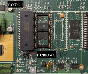
The attached Intel HEX file has to be programmed into a chip. If you don't have a chip programmer you may be able to find someone local to help (maker groups, community college, etc.). This firmware is very small and can use a cheap 5v flash chip* readily available from Digikey/Mouser (currently $2.89). It can also be programmed into a 512kB or 1MB EPROM chip, if you already have one, by changing the 1st line of the HEX file (see post #3).

*SST39SF010A-70-4C-PHE 128kB flash in 32-PDIP package

<remove .txt from hex file name>
 

Attachments

Last edited:
Instructions:
Wear a grounded anti-static wrist strap when handling any chips.

Be very careful to not bend any pins when removing/inserting a chip. Pins on new chips are spread too wide and you may want to carefully bend the pins in a little first by gently pressing all pins on one side against a hard surface.
  1. Completely power off panel (disconnect transformer and battery).
  2. The firmware chip will go into the leftmost socket (U29). Remove anything (chip or module) plugged into that socket and insert the firmware chip. The notch on one end of the chip should be at the top of the socket (see attached pic).
  3. Remove jumper JP10 below U29 socket (non-flash panels won't have this).
  4. Plug in the transformer only (no battery). Within 1 second the PHONE/STATUS leds should start blinking (1x/second). Alternating blinks (one led at a time) indicates success. Both blinking together indicates some checks failed and the firmware didn't do anything (PM me for further instructions).
  5. Completely power off panel
  6. Remove the firmware chip and reinstall any chip/module removed earlier. The chip will fit very tight the first time and be hard to remove. Don't yank up one end or you'll ruin the pins. Gently lift each end, alternating a little at a time, until the chip comes out. If using any tools for removal be VERY careful not to knock parts off the board--I sometimes use an angled pick to pry the chip out but put something hard on the pcb to protect it.
  7. Replace jumper JP10 if removed
  8. Reconnect battery and power up panel normally
Troubleshooting:
  • leds on but not blinking: forgot to remove jumper JP10, bent chip pin not in socket, or chip programmed incorrectly
  • both leds blinking together rapidly (2x/second): attempted write but verify failed
 

Attachments

  • chip-install.jpg
    chip-install.jpg
    222.4 KB · Views: 0
Last edited:
To program this firmware into different size chips, replace the first line of the HEX file with one of the following:

chip size1st line of HEX file
128kB:020000040001F9
512kB:020000040007F3
1MB:02000004000FEB

Any modern chip programmer can read the HEX file. But if for some reason you need a full binary image file, create it using SRecord tools (included with Linux or download Windows version):
Code:
128kB:
  srec_cat -output reset128.BIN -Binary reset_instcode.hex -Intel -fill 0xFF 0x0 0x20000

512kB (use modified HEX file):
  srec_cat -output reset512.BIN -Binary reset_instcode512.hex -Intel -fill 0xFF 0x0 0x80000

1MB (use modified HEX file):
  srec_cat -output reset1MB.BIN -Binary reset_instcode1MB.hex -Intel -fill 0xFF 0x0 0x100000
 
Last edited:
Back
Top