SUCCESS!
I've successfully tested a firmware mod that adds a new feature to my OmniProII panel! Still very early lab prototyping but the concept has been confirmed.
I want my panel to transmit a digital Contact-ID (CID) alarm report to an external processor that can then send a real SIA DC-09 IP alarm report to a central station (see
post #32 about avoiding delays and middlemen like Alula, etc.). I located the firmware that generates the CID checksum and added code to transmit each message byte over the SPI interface. The SPI interface normally communicates with hardwire expanders and is on that connector. I don't have any hardwire expanders so thought SPI was unused. Nope, of course the Omni sends a polling message over SPI every 10ms, even when no expanders are configured, so I had to locate and disable that polling code. I may switch to using a serial port instead.
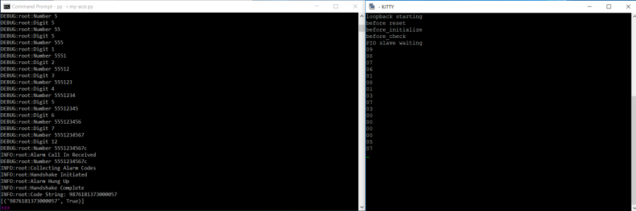
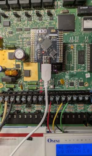
The attached screen shot shows 2 windows. The left shows my telephone central station emulator (
post #24) receiving a Fire Trouble alarm report from the panel (phone number 5551234567#, CID msg 9876181373000057). The right shows a serial terminal receiving the same CID message from a RPi Pico2 listening to the Omni SPI interface
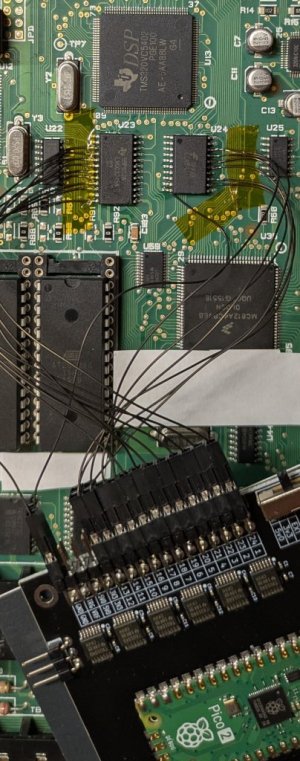
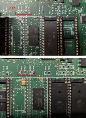
A big time saver was the EPROM emulator I made (software based on
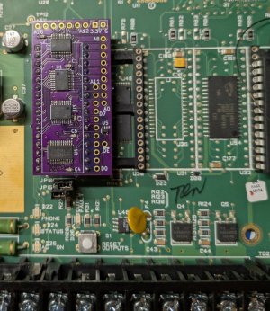
this project). I can load a rom image onto the emulator in less than a second and start running immediately. I couldn't use one of my $5 Pico2 (not enough IO pins) so I had to get a $7 Pico2 "XL" (really a WeAct RP2350B with 48 IOs). With 520kB of SRAM it can emulate a 512kB EPROM. I also made a custom pcb to plug into the EPROM socket and hold the interface translator chips that allows the 3.3V Pico2 to safely connect to the 5V Omni panel.
The emulator opens up a bunch of new capabilities. For example I can make a small service code firmware that can run from the emulator and be used to read/write the flash chips on the panel making it possible to repair a corrupted flash image.