HAI Omni engineer/developer thread

I've been busy with other projects but did finally trace out the phone circuit on my OmniPro II (schematic attached). There's not much in the audio path to go wrong. Besides a bad capacitor or leaky transistor/protection-device, the only thing is audio codec U3.
I have a board I bought way back on ebay as a backup but never tested. Cant see phone line, been trying to draw out the chema for that section for a while. Thanks!
 
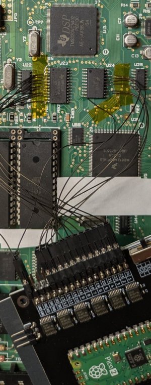
I've done some more OmniPro II reverse engineering after deciding to learn about the incredible power of the $5 RPi Pico2's programmable io (PIO) state machines. So I used PIO to implement bus capture of the communication between the OP2 cpu and dsp.

Why? I have a vague idea of implementing direct digital IP alarm reporting without analog dial-out DTMF generation/decoding (10-20 second delay) and third party middlemen (Alula, etc.) adding more delay and extra cost.

I've captured dsp bus reads/writes for a dial out report and see how it sends phone number digits (1 at a time, probably waits for status after each) then the Contact-ID message (first 4 digits, account number, also 1 at a time then next 12 digits consecutive writes). With this info I could implement a very clunky/crude IP communicator but it would need my analog central station emulator from post #24 to fool the OP2.

Best result would be finding the firmware code that handles a dialout report, bypassing all of the phone related parts and just sending a simple digital message to an external mcu/ethernet board which handles all the IP alarm details.

I also updated the dsp info in post #25.
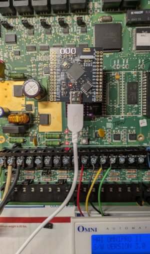
Picture shows my wired up Pico2 "logic analyzer" which just has level translators that aren't even needed here because the dsp io is 3.3v.

EDIT: This may not be as impossible as it sounds. I've located all firmware code that communicates with the dsp and I've isolated 2 routines that send DTMF tones for phone number and contact-ID report. My bus capture trace has the dsp responses that indicate success so I have everything I need to bypass that code. To speed testing/debugging I may make an EPROM emulator out of one of my Pico2 boards (limit of 512KB so 3.x firmware?).
 

Attachments

  • pico2-capture.jpg
    pico2-capture.jpg
    126.2 KB · Views: 16
Last edited:
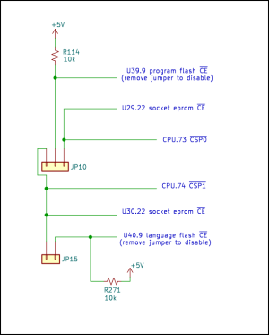
Here's a schematic of the EPROM jumpers described in post #16. The flash chip is completely disabled by removing the jumper, perfect if you want to use the EPROM socket for an emulator or a chip with different firmware. HAI likely used this for initial/recovery programming of the firmware flash.

EDIT: I've confirmed this on a 4.0b firmware flash board by removing the JP10 jumper and installing a 3.0 chip eprom. The panel started up after a short delay and showed 3.0 firmware. It erased the installer code and other things (DCM phone number, etc.) in the CPU internal eeprom but other setup info seems to be there. Removed the eprom chip and put back JP10 jumper and panel starts up with 4.0b firmware. We now have a easy way to reset installer code on a flash board!
 

Attachments

  • HAI-OmniProII-EPROM-Jumpers.png
    HAI-OmniProII-EPROM-Jumpers.png
    40 KB · Views: 10
Last edited:
While waiting for parts to build a ROM emulator I've been doing deep dives into the firmware. I've found non-standard things that cause problems for standard tools such that even if an awesome former developer gave us the source code we couldn't build it without modified tools.

Example: the firmware uses SWI (software interrupt) instruction to implement system calls, but it adds a byte after the SWI as an index into a lookup table of function addresses. That byte is worked around by the SWI handler but it confuses a standard disassembler. I had to modify my disassembler to treat that byte as an operand to SWI:

Code:
Standard disassembler:
            psha                                    ;$0000 $36
            tfr     CCR,A                           ;$0001 $B7 $20
            bita    #$10                            ;$0003 $85 $10
            bne     L0009                           ;$0005 $26 $02
            swi                                     ;$0007 $3F
            sbca    L0032                           ;$0008 $92 $32
            rts                                     ;$000A $3D

Modified disassembler:
            psha                                    ;$0000 $36
            tfr     CCR,A                           ;$0001 $B7 $20
            bita    #$10                            ;$0003 $85 $10
            bne     L0009                           ;$0005 $26 $02
            swi     #$92                            ;$0007 $3F $92
L0009       pula                                    ;$0009 $32
            rts                                     ;$000A $3D

I've been updating many older posts in this thread as I discover new information.
 
SUCCESS!

I've successfully tested a firmware mod that adds a new feature to my OmniProII panel! Still very early lab prototyping but the concept has been confirmed.

I want my panel to transmit a digital Contact-ID (CID) alarm report to an external processor that can then send a real SIA DC-09 IP alarm report to a central station (see post #32 about avoiding delays and middlemen like Alula, etc.). I located the firmware that generates the CID checksum and added code to transmit each message byte over the SPI interface. The SPI interface normally communicates with hardwire expanders and is on that connector. I don't have any hardwire expanders so thought SPI was unused. Nope, of course the Omni sends a polling message over SPI every 10ms, even when no expanders are configured, so I had to locate and disable that polling code. I may switch to using a serial port instead.

The attached screen shot shows 2 windows. The left shows my telephone central station emulator (post #24) receiving a Fire Trouble alarm report from the panel (phone number 5551234567#, CID msg 9876181373000057). The right shows a serial terminal receiving the same CID message from a RPi Pico2 listening to the Omni SPI interface

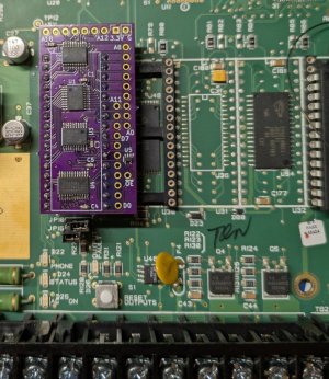
A big time saver was the EPROM emulator I made (software based on this project). I can load a rom image onto the emulator in less than a second and start running immediately. I couldn't use one of my $5 Pico2 (not enough IO pins) so I had to get a $7 Pico2 "XL" (really a WeAct RP2350B with 48 IOs). With 520kB of SRAM it can emulate a 512kB EPROM. I also made a custom pcb to plug into the EPROM socket and hold the interface translator chips that allows the 3.3V Pico2 to safely connect to the 5V Omni panel.

The emulator opens up a bunch of new capabilities. For example I can make a small service code firmware that can run from the emulator and be used to read/write the flash chips on the panel making it possible to repair a corrupted flash image.
 

Attachments

  • fw-mod-success.png
    fw-mod-success.png
    54.6 KB · Views: 5
  • emulator-interface.jpg
    emulator-interface.jpg
    121.5 KB · Views: 6
  • emulator-run.jpg
    emulator-run.jpg
    95.1 KB · Views: 6
Last edited:
Wow, I actually finished what I set out to do in post #32. My new modded firmware (only 11 overwrites + 24 bytes of new code!) does true instant digital communication of Contact-ID alarm reports, no relays clicking or phone line seizing at all. My first firmware mod in the previous post "piggybacked" onto an existing dcm communication which required a phone line, alarm receiver sending handshake and acknowledge tones, etc. The new mod doesn't need any of that, it truly bypasses all of the phone related parts.

The absolute fastest the old telephone dcm can communicate a report is 11 seconds and that is to a local receiver (like Alula)--landline, VOIP or cell would add even more delay plus inevitable retries. The new digital communication takes 1.47ms (to local receiver).

I learned a lot about the HAI firmware. It uses a primitive RTOS or task scheduler with a 10ms tick. This code from the phone dialer shows how it schedules the 2-second pause for a 'T' in the phone number using a swi (software interrupt) to sleep for 200 ticks:

Code:
            cmpb    #$54      ; 'T' pause           ;$D18A $C1 $54
            bne     LD197                           ;$D18C $26 $09
            pshx                                    ;$D18E $34
            ldx     #$00C8    ; 200                 ;$D18F $CE $00 $C8
            swi     #$AE      ; 200*10ms pause      ;$D192 $3F $AE

This is all just for educational purposes and will go through a lot of testing on my lab bench. At some point I will test it under a real load on my home system, but of course only sending reports to my simulated digital receiver.
 
Last edited:
I've been working on a small standalone service firmware for diagnostics/repair. One interesting discovery is that the 2 flash chips seem to have the exact same data but in different places. I've also found firmware code that copies data from one flash chip to another so there may already be a recovery routine in a super secret HAI service menu.

Firmware flash chipLanguage flash chip
1MB empty1MB language data
1MB empty1MB firmware
1MB language data1MB empty
1MB firmware1MB empty

In normal operation the CPU can only address 2MB per chip. My special firmware along with setting the jumpers just right allows the cpu to access the full 4MB of one chip (wasn't easy, have to copy code into the cpu internal SRAM and run from there).

The more I go through the firmware the more impressed I am with what the engineers were able to achieve with severe limitations. But I have a great deal of disdain for the atrocious system architecture that led to HAI's demise. The 8MHz cpu effectively runs like a 2MHz cpu because 16-bit instruction fetches go over an 8-bit bus and there's 1 extra stretch cycle added to each bus access so each instruction fetch takes 4 cycles. A simple branch takes 12 cycles. It was at its absolute limits at the end.

The main board at most should have done security-only, all automation could have been on a separate cpu card on the expander connector. The automation card wouldn't need expensive UL certification and could have been updated every year with minimal cost.
 
SUCCESS!

I've successfully tested a firmware mod that adds a new feature to my OmniProII panel! Still very early lab prototyping but the concept has been confirmed.

I want my panel to transmit a digital Contact-ID (CID) alarm report to an external processor that can then send a real SIA DC-09 IP alarm report to a central station (see post #32 about avoiding delays and middlemen like Alula, etc.). I located the firmware that generates the CID checksum and added code to transmit each message byte over the SPI interface. The SPI interface normally communicates with hardwire expanders and is on that connector. I don't have any hardwire expanders so thought SPI was unused. Nope, of course the Omni sends a polling message over SPI every 10ms, even when no expanders are configured, so I had to locate and disable that polling code. I may switch to using a serial port instead.

The attached screen shot shows 2 windows. The left shows my telephone central station emulator (post #24) receiving a Fire Trouble alarm report from the panel (phone number 5551234567#, CID msg 9876181373000057). The right shows a serial terminal receiving the same CID message from a RPi Pico2 listening to the Omni SPI interface

A big time saver was the EPROM emulator I made (software based on this project). I can load a rom image onto the emulator in less than a second and start running immediately. I couldn't use one of my $5 Pico2 (not enough IO pins) so I had to get a $7 Pico2 "XL" (really a WeAct RP2350B with 48 IOs). With 520kB of SRAM it can emulate a 512kB EPROM. I also made a custom pcb to plug into the EPROM socket and hold the interface translator chips that allows the 3.3V Pico2 to safely connect to the 5V Omni panel.

The emulator opens up a bunch of new capabilities. For example I can make a small service code firmware that can run from the emulator and be used to read/write the flash chips on the panel making it possible to repair a corrupted flash image.
Using a serial port would, IMO, be a much better option than the SPI bus for a few reasons. That said, if this is a mod, just for you, then leave it alone. If it is something you would want others to be able to use an implement, then hijacking a specific serial port for this use may be better, if it can be done. I personally would love the ability to abandon an analog interface for monitoring in lieu of a digital interface.
 
For what it's worth I've confirmed that the 4.0b firmware and language data in both flash chips are identical with each other and with the chip eproms. The language data exactly matches the 20A05-2 2.0 eprom chip I copied from my 20 year old panel. But I'm not sure where the 4.0b firmware file that's floating around came from, was there ever a 4.0b chip eprom or did someone extract it from flash or an update file?

Using a serial port would, IMO, be a much better option than the SPI bus for a few reasons. That said, if this is a mod, just for you, then leave it alone. If it is something you would want others to be able to use an implement, then hijacking a specific serial port for this use may be better, if it can be done. I personally would love the ability to abandon an analog interface for monitoring in lieu of a digital interface.

I have to do a lot of testing before getting there but might do that if my mod is stable with real world inputs. I'm using a W6100-EVB-PICO2 to interface between the panel (SPI or serial) and internet (ipv4 or ipv6). That's where others could really get involved with pico2 firmware and phone apps for alarm control, status and automation.
 
For what it's worth I've confirmed that the 4.0b firmware and language data in both flash chips are identical with each other and with the chip eproms. The language data exactly matches the 20A05-2 2.0 eprom chip I copied from my 20 year old panel. But I'm not sure where the 4.0b firmware file that's floating around came from, was there ever a 4.0b chip eprom or did someone extract it from flash or an update file?
The 4.0B firmware was released on eprom for the Pro2, 2e and LT (not the LTe). Boards sent in for repair to Leviton would be returned with the 4.0B eprom. I had this happen to a number of boards I sent in. I have those firmware files if you are interested.
 
I've sucessfully tested erasing and programming the flash memories in-circuit using my service firmware. I verified this on both flash chips confirming my understanding of the chip selects and extended addressing interactions. In theory I can now unbrick a panel that got bricked during an update.

I ported my digital alarm reporting firmware patch to 4.0B, and all the changes are within 1 sector*, so I erased and wrote that sector in the firmware flash on my board. It is working the same as it did when running patched 3.0 firmware on the EPROM emulator so the next step is to install the panel in my house system and see what happens.

(*The AMD Am29F032B 4MB NOR flash chips use 64kB sectors which means if you want to change just 1 byte with any bit changing from 0->1 you have to erase and rewrite all 64kB in that sector.)

One request: the firmware has flash unlock sequences for 2 different types of chip and I can't identify the other one; if anyone has a panel with any flash chip different from Am29F032B please post the part number here. EDIT: I think it is S29GL064N90TFI02 or S29GL032N90TFI02 used on that weird pcb that covers the 2 EPROM sockets on some non-English systems.
 
Last edited:
I've sucessfully tested erasing and programming the flash memories in-circuit using my service firmware. I verified this on both flash chips confirming my understanding of the chip selects and extended addressing interactions. In theory I can now unbrick a panel that got bricked during an update.

I ported my digital alarm reporting firmware patch to 4.0B, and all the changes are within 1 sector*, so I erased and wrote that sector in the firmware flash on my board. It is working the same as it did when running patched 3.0 firmware on the EPROM emulator so the next step is to install the panel in my house system and see what happens.

(*The AMD Am29F032B 4MB NOR flash chips use 64kB sectors which means if you want to change just 1 byte with any bit changing from 0->1 you have to erase and rewrite all 64kB in that sector.)

One request: the firmware has flash unlock sequences for 2 different types of chip and I can't identify the other one; if anyone has a panel with any flash chip different from Am29F032B please post the part number here. EDIT: I think it is S29GL064N90TFI02 or S29GL032N90TFI02 used on that weird pcb that covers the 2 EPROM sockets on some non-English systems.
Are you asking specifically about an alternate 4mb flash chip?

-The earlier boards used the 1mb flash chip (M27C801-100F1)
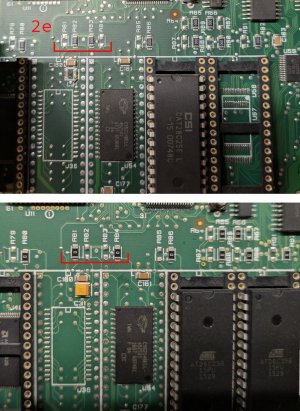
-The last production boards had the S29GL032N90TFI02 on the daughter board.

I have an controller with the daughter card that was factory loaded with 4.0A. I have not taken the time to pull the firmware to compare it to 4.0b. not sure if the A variant was for the daughter board versions and the B variant was for the older implementations or something else. Anyone else know?
 
Are you asking specifically about an alternate 4mb flash chip?

-The earlier boards used the 1mb flash chip (M27C801-100F1)
-The last production boards had the S29GL032N90TFI02 on the daughter board.
Thanks for confirming that part number. I could only see part of a number in a blurry pic but that was enough to confirm a match with the erase/program code in the firmware.

The earlier boards used a 512kB EPROM chip (M27C4001) for firmware and later when it got bigger used a 1MB EPROM chip (M27C801). The language chip was always a 1MB M27C801. These are not flash chips and cannot be programmed on the board.

Newer boards use two 4MB flash chips (Am29F032B - 40 pins) soldered to the board under the EPROM sockets. These cannot be removed for programming which is why I had to develop a method for programming them in place.

The daughter card you have uses a single 56-pin 4MB flash chip presumably because the Am29F032B went out of production. Have you tried to upgrade to 4.0B with PC Access? Depending on the design of that card it might just work or it might possibly require the EPROM jumpers to be set in a special way for programming. I don't know anything about that card--can you post close up macro pics of the front and back?
 
Back
Top