Hi
I have a simple question. What are the pin-out for the "Control In" side of the ELK 952?
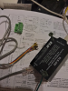
The manual for it does not specify and says the cable is not included. The ELK 952 came with my ELK M1 and this little pigtail was included. Is this what I'm suppose to use? If so, then I guess I need to snip the ends off to fit into the Panel Connector? I do not know the correct pins in this interface, so I do not really know if this provided pig tail is correct..
If I knew the pin-out for this interface I could just crimp up a RJ45 8 pin connector and make sure the colors for wires Green, Red, Brown, Grey match to the correct slot in the 8-pin connector going into the ELK 952 "Control In".
Thanks!
I have a simple question. What are the pin-out for the "Control In" side of the ELK 952?
The manual for it does not specify and says the cable is not included. The ELK 952 came with my ELK M1 and this little pigtail was included. Is this what I'm suppose to use? If so, then I guess I need to snip the ends off to fit into the Panel Connector? I do not know the correct pins in this interface, so I do not really know if this provided pig tail is correct..
If I knew the pin-out for this interface I could just crimp up a RJ45 8 pin connector and make sure the colors for wires Green, Red, Brown, Grey match to the correct slot in the 8-pin connector going into the ELK 952 "Control In".
Thanks!