I would use the "True RMS" split core current transformers with the 4-20 ma output (better for long cable runs and is more noise immune).
You should also be measuring voltage as well as WATTS = VOLTAGE * CURRENT, but again, the voltage probably doesn't change all that much and you could get away with using a standard measured value.
"True RMS split-core current transformers" are by definition _averaging_ devices (RMS = Root-Mean Squared; the mean is an average). These are useful but expensive new because they need to embed the circuitry to calculate RMS from the AC signal.
And to clarify, they are not what one wants for very accurately calculating _instantaneous_ " watts = volts * amps" because to do this with greatest accuracy, the calculations need to be performed at many times during the AC cycle especially with noisey loads such as conventional TRIAC dimmers.
One potentially less expensive route to 'complete satisfaction' that provides an upgrade path to 'instantaneous V*I calculation' is to use multiple less expensive, conventional (instantaneous) current transducers through a multiplexor and 'read' by a single RMS conversion circuit.
So numerous Current Transformers, Shunt Resistors, or a mix of CT's and SR's can share a single RMS (or other ) converter and Analog -to-Digital Converterinp
CT -- +
SR -- |
CT -- | Multiplexor ---> RMS converter ---> ADC
SR -- +
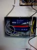
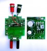
Attached is a picture of surplus RMS converter circuit board. I obtained a dozen of these on eBay for a few dollars each.
The inset photo shows the actual RMS converter IC on the PCB.
One can then measure the output of the RMS converter using (eg) Peter Anderson's nifty offerings and either measure or assume the AC voltage ( eg 115vac) needed for the V * I calculation.
An advantage of this approach in my experience is that the hardware can be improved incrementally depending on actual need experienced It's easy to imagine that you need more accuracy than you really do.
If you buy expensive "True RMS current transducers" and then decide that you need instantaneous V*I calculation, your investment in Time and Treasure is for nought..
But if you determine that using the AC voltage at the (eg) entrance panel is not accurate enough owing to (eg) voltage drop in the AC distribution conductors in your house, one can add the required local AC measurements through a small wall-wart and do the calculations with that, more accurate, data on an as-needed basis.
CT --- +
CT --- |
CT --- | Multiplexor ---> RMS converter --> Analog-to-Dgital --> Software Multiplier
CT --- |
VAC --|
VAC --|
VAC --|
VAC --+
And if you then decide that you need instantaneous V*I measurement, you can substitute a V*I calculator and have obsoleted only *one* component of your installed system, namely the RMS converter.
CT --- +
CT --- |
CT --- | Multiplexor ---> Analog-to-Dgital converter +
CT --- | |
+ --> Instantaneous V * I calculator
VAC --| |
VAC --| Multiplexor ---> Analog-to-Dgital converter +
VAC --|
VAC --+
The V*I calculator could be a specialized IC such as the SAMES ICs I reference elsewhere in this thread, a homebrew analog circuit such as what Ed Cheung has documented, the Watt Meter Michael McSharry describes, a PC with few enough tasks to be near real time, or a micontroller such as a Basic Stamp, BX-24, PIC or AVR. I am partial to teh AVr solution and will post a PCB and circuit time permitting. It uses the free (for no-commerical use) version for Eagle CAD software ( www.cadsoftusa.com)
and code that might be compact enough to be compiled with the free version of BASCOM AVR basic (www.mcselec.com ) .
I'll try to consolidate this at my www.ECOntrol.org web site over the next week or so.
HTH .. Marc