You are using an out of date browser. It may not display this or other websites correctly.
You should upgrade or use an alternative browser.
You should upgrade or use an alternative browser.
4 Wire PIR to OmniPro ii
- Thread starter abernut
- Start date
pete_c
Guru
@Mike,
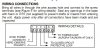
Attached is a diagram. You can also wire in the tamper switch to the same loop or a separate loop (for 6 wires). Personally I have installed my EOLs here soldering them and then using heatshrink tubing. Its up to you if you are going to utilize EOL's or not. It is an all or nothing thing with the OPII.
I use PCA to watch and test here with my OPII panel when adding stuff like this.
1 - If using 22/4 the wire colors are typically Red, Black (good choice for the 12VDC), White and Green (good choice for the switch). Note here I just looked at a yellow 22/4. Colors may very.
2 - pick a zone pair you want to utilize and the 12VDC.
3 - do your EOL stuff if you are using it.
4 - my values here on the EOL terminated PIRs are around 148 on PCA.
Easy stuff; just do baby steps.
Attachments
I ran 22/4 (Red, Black, Yellow, Green) through out the entire house and just wrapped the unused pair around the wire at the OmniPro ii. This way if I need it, it is there.
I have 1K ohm resistors on all of my other contacts in the house so I assume I will need it on the PIR.
Would I just solder a 1K Ohm resister to the contacts on the board?
I also used PC Access to configure my current zones. So far they have all been perimeter zones. What type is the PIR
On the PIR would I use:
1 - Red
2- Black
3 - Green
4 - Yellow
The Red and Black would go to a power source on the omnipro and the Green and Yellow would go to an available zone?
Thanks for your help.
Mike
Have you taken a look at the installers manual? You can find a copy here:http://www.smarthome.com/manuals/110604install.pdf
Zone hookup is on page 5. Zone type setting is on page 37. Interior motion sensors are typically set as "AWAY INTERIOR"
The EOL resistors go in series for normally closed sensors like a motion detector. The only rule is you need to install the resistor in the motion sensor and NOT in the panel if you want it to be of any use. (EOL resistors are not required, but if you use one on one zone on the OMNI, all zones need to have one.)
pete_c
Guru
That is also what I have done here. I did solder the EOL resistor at the end of the wire such that the other side of the resistor is connected to the terminal. I used one of those little mini propane torches or soldering device.The only rule is you need to install the resistor in the motion sensor and NOT in the panel if you want it to be of any use
I then put the heat shrink tubing over the end with the EOL resistor wire coming out.
Nothing against soldering and shrink tubing, especially if space is really tight, but once you start using these little splice connectors, it will change your life:
http://www.amazon.com/s/ref=nb_sb_noss?url=search-alias%3Daps&field-keywords=scotchlok%20UY2
They are filled with a gel that protects the conductors, and with a pliers in under a second that are connected for good. I use MANY and I've yet to ever see one fail. If you look through the back of them, you can even visually verify the wires are connected. I certainly wish I had invented them.
I should add, if you do buy these, buy the ones made by 3M, not the cheaper copies. These are junk.
These motions are kicking my butt.
I currently have:
+ of the PIR to the +12V on the omnipro.
- of the PRI to neutral on the omnipro
R of the PRI to the first terminal of zone 22 on the omnipro.
R of the PRI to the second terminal of zone 22 on the omnipro.
For testing I wired a 1K OHM resistor in series at the board. The panel always showed the motion Not Ready.
I then removed he resistor and changed the settings of the omnipro to not use EOL. The panel always showed the motion Not Ready.
I did not wire anything into the tamper loop because I left my soldering gun at work.
What am I over looking?
Thanks guys.
Have you checked the wires from the panel to the PIR for continuity? If the wire checks out ok, then use a multimeter to check the wires at the panel end to see if the contact on the PIR is really closed or not. Then you should know whether the problem is with the PIR itself, or something with the panel.
pete_c
Guru
To test the circuit I ran a small 1ft 22/4 from the panel the PIR so I know it's not a bad wire.
You mean you tested the PIR with a small 1 ft 22/4 wire and the PIR worked; eh?
pete_c
Guru
I do not remember any more. Looking as they are in the Leviton can.
The spares are in a little unmarked plastic bag in the HAI can. There are some Radio Shack resistors there too..
The RS ones are 1K 1/2 watt and testing with a multimeter the unmarked back and they are the same.
There are also Radio Shack 100 Ohm packs and 1 pack with 1 Megohm resistors.
I do recall having an issue once purchasing the incorrect valued ones ones for a bit. I did post here about the issue a while ago.
Initially here started with no EOL resistors then did a revisit and put them in.
Guessing the ones I used are the 1K resistors. My loop values would be different had I used a different resistor.
I am guessing though if you aleady get the right values with what you already have put in; then it should be the same with the new PIRs.
Curious what are you loop values?
Mine as stated early sit around 149 or so in the normal state. Just triggering a PIR watched the loop value go to 253.
This is what I did. It worked for me relating to testing each run of wires. Go slow; starting initially with baby steps
The more checking you do; the faster it becomes.
BTW validate your wires with a multimeter first; then worry about the EOL resistors afterwards. I have also used an old flashlight here with a plug at the end of it which connects to two cable clips. Old; simple the light goes on when there is continuity. Still works here; must be like 40 years old.
Just leave the wires bare on each end. Personally here utilize little jumpers. I use the continuity beeper on the multimeter. Short out one pair of wires on one side; then go to the other side and connect or touch your multimeter to same two wires. If it beeps then there are no breaks in the wire. Move on to the next pair; you can use one wire to the three other wires for your pairs. Test each one wire this way.
Once you have established the continuity of the wires then connect the power wires (red and black) to the PIR. Leave the other pair off for a second. Wave your hand in front of the PIR; the little LED inside should blink and you might hear the little relay inside of the PIR clicking. This is just to validate that the PIR functions with 12VDC. Now connect the panel zone ends leaving the wires not connected at the PIR end. Use a jumper on those two wires which are connected to the zones on the PIR end or just twist the wires together. Look at PCA and see your loop value. Then take your resistor and hand twist it to one of the two wires. Then twist the other side of the resistor to the other wire. Look at your loop value. It should have changed. Then connect the two leads to your PIR. Take a laptop in the same room and load up PCA and connect to your panel and look at the ZONE status. Wave your hands in front of the PIR and watch the value change.
Similar threads
- Replies
- 13
- Views
- 495
- Replies
- 0
- Views
- 113
- Replies
- 53
- Views
- 1K