tattema
Member
Never
LOL, I really enjoyed reading your story and could relate to it 100%. If you end up commercialising your ideas then I guess you can just re-visit your design or opt for the originals.
It's possible however that the range problem you experience with the original Nordic chips and other copies could be related to PCB design? When I designed my RF module, the first version had a horrible range because I didn't really consider the output stage impedance. With the second version, I made sure that the impedance was almost a perfect 50 Ohms and worked with the PCB manufacturer to ensure that all the parameters were correct. e.g. dielectric constant for the PCB epoxy, space between the track and ground plane and finally the actual track width/length. I must admit that I was a little annoyed with myself for not thinking the output stage through when I designed the first module but the results and range I got from the second version were excellent. Mental note... pay attention to the details, especially with RF.
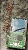
Here's a module panel, unpopulated, manufactured through a Chinese company. They did a perfect job.
.jpg")
NeverDie said:That was my first reaction as well. Then what next blew me away was finding out there are at least a dozen different known clones of it: http://www.testandmeasurementtips.com/embedded/pocketpico-p200-powermate/
plus who knows how many other clones out there "in the wild" as it were.
The original motivation for that mysensors thread was me being disappointed in some NRF24L01+ modules that I had purchased................... In the end it may turn out that the transmission current will help differentiate fakes from the genuine article, but the curious twist is that I may have found a cheap fake that I actually prefer!
LOL, I really enjoyed reading your story and could relate to it 100%. If you end up commercialising your ideas then I guess you can just re-visit your design or opt for the originals.
It's possible however that the range problem you experience with the original Nordic chips and other copies could be related to PCB design? When I designed my RF module, the first version had a horrible range because I didn't really consider the output stage impedance. With the second version, I made sure that the impedance was almost a perfect 50 Ohms and worked with the PCB manufacturer to ensure that all the parameters were correct. e.g. dielectric constant for the PCB epoxy, space between the track and ground plane and finally the actual track width/length. I must admit that I was a little annoyed with myself for not thinking the output stage through when I designed the first module but the results and range I got from the second version were excellent. Mental note... pay attention to the details, especially with RF.
Here's a module panel, unpopulated, manufactured through a Chinese company. They did a perfect job.


")