Controlling house zones using a wood boiler

gabir

Member
Hi, firstly let me say that I am quite impressed with webcontrol even if I am not a programmer and I am learning the basics of PLC. I have a new mission for it, so explained. I used a dual fuel boiler, to heat my house, oil and wood. Teh boiler heats waer which is then pumped to radiators around the house. When the boiler is fired as oil, the oil burner is triggered by 4 zones thermostats, each calling for heat, until there is enough hot water stored inside the boiler or the thermostat in that zone being satisfied. Once this happens the oil burner stops until the cycle is repeated as needed. If I fire it as a wood bolier however, things are quite different. Wood fire can't be controlled as quiclkly, so it will burn more or less until all wood is consumed. I would like to ask your help with these basic 3 functions (the first of which will have to be multiplied for each of the zones):
1) temperature is sensed in a zone and the pump for that zone is switched on if below a set temperature and switched off if higher, with about 2 degrees hysteresis so that the pump doesnt cycle too often.
2) temperature is sensed in the boiler, and if it is below a set point all pumps are switched off. This is to avoid that the pumps keep circulating if no heat is available.
3) temperature is sensed in the boiler and, at a specific set point, a zone is activated. At that setpoint +10 degreees a second zone is activated. This is for protection, should the temperature in the boiler get too hot, then even if the zones do not call for heat they are activated sequentially and the heat from the boiler dissipated. Once the boiler temp falls below this set point all functions return to normal.

I would much appreciate help with the above, some or all, in setting up a basic PLC programme for these functions. I am using the new version 03.02.16b.
Thanks!
Gabir
 
When you sensing temperature in a zone, what kind of temperature range do you expect? If it is water temperature, you could use those DS18B20 sensor. If temperature is in the burning chamber, then you will need to use different sensor, maybe oven sensor, connecting to the analog input.

In your case #1, you have a pump that need to be turned off at a set temperature. In the case #2, you have pumps that need to be turned off at setup point. Supposedly those are different pumps and the set point temperatures are different, too?

Thanks for using WebControl. We love to help people to automate things around their offices, labs, and homes. We will work with you for the solution.
 
Thanks. The ranges are within the specs of the DS18B20 (–67°F to +257°F). For the zones: 40 to 80 F. For the boiler the low setpoint should be around 60F and the high setpoint at about 180F. I have the webcontrol wired in and I am logging the temps to that effect. It is very accurate with only a decimal point or so of variation as compared to a commercial digital thermometer. I dont have any very long runs on the sensor wires (I will soon have to set up some, we will see)

To answer your questions:

In reference to my point #1 each zone pump is turned on when the temp in that zone falls below the set temperature (which will be between 40-70F). This is exactly the same as a regular heating thermostat setting in a house. In point #2 all pumps are turned off when the temp falls below 60F as measured at the boiler. Once the temperature at the boiler reaches 60F, then each zone willl resume control of their relative pumps. In my point #3, one of the pump will turn on when the temp in the boiler goes over 180F regardless of what the temp in that zone is. (This is a fail safe measure to avoid too much of a high temp in the boiler, as a pump turns on some heat is dissipated.)

Yes they are 4 different zones/pumps and they should be able to be set at different temperatures for each zone.

Thanks again!
 
Another question... :blink: I am using 4 very small 5V ttl coil relays, which are so far powered by pin 13, ground and each triggered by their respective ttl ouputs (1-4). Each needs 15-20mA driver current. I am using an 8.5 V 1.5 A power supply to power the webcontrol. The question is what kind of currrent can I draw from pin 13 without any overheating issues?

Not sure how to thank you but here is another thank you!

the relay board is here
 
If you have 20mA relay coil directly connected to the TTL output, please make sure you have a diode to bypass the spike caused by the TTL output turned off, that can kill the output chip easily. Another thing is to make sure not exceed 20 mA current on TTL output and total not exceeding 100mA on all the TTL output combined.

The 5V load is driven by the big regulator. If that is overheated, then it can broken down. Currently, there is no heatsink connected to that regulator. You may consider adding heatsink to that if you want the pin 13 provide 5Vs to the relays.

You have four zones and four pumps, Each zone has its own temp sensor.
You start with
START
END

then add your first logic, which is critical turn on pumps at 180F.

START
TSTGE T1 1800
SET OP1 1
TSTGE T2 1800
SET OP2 1
TSTGE T3 1800
SET OP3 1
TSTGE T4 1800
SET OP4 1
END

Now, we assume OP1 control pump1, op2 control pump2, etc.
But your point#1 and point#2 logic have conflict, you said if temp reach set point between 40 to 70, you turn the pump on. However, in your point#2, when temp reach 60, you turn pump off. These two rules are conflicting, since 60 is within the range of 40-70.

Could you please clarify?
 
thanks. the heathsink sounds like a good idea.
Here is the clarification. Point 1 refers to the ambient temperature in any of the zones. Point 2 refers to the temperature of the water in the boiler. If the temperature of the boiler is too low, then there is no point for any of the pumps to start, because they would pump cold water. so the temperature in the boiler (point 2) has to be at least 60 for any of the pumps serving the zone to be able to turn on, if their zone calls for it. I hope that clarifies.
thanks again.
 
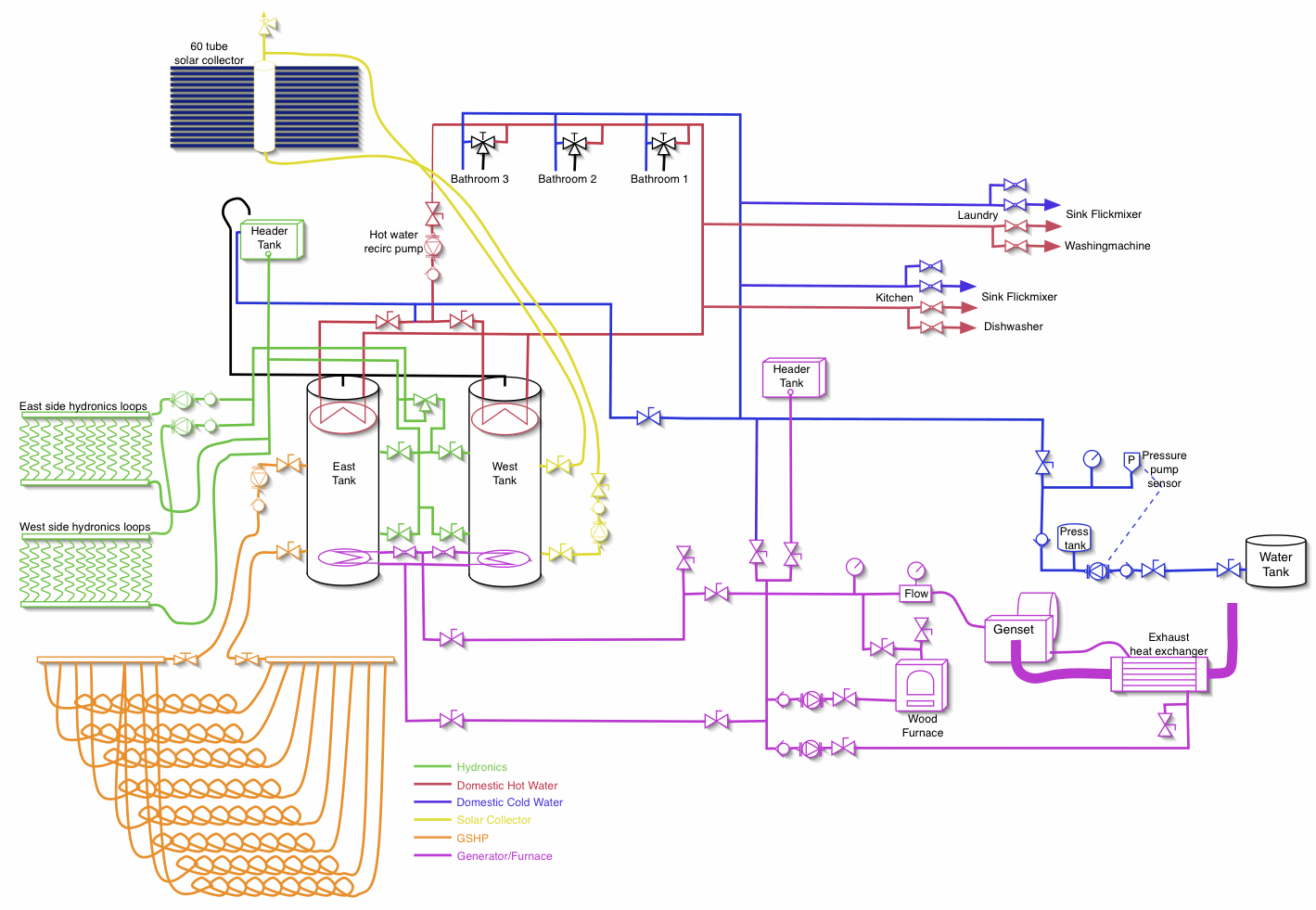
I have a sort-of similar arrangement here.

I have 10KW cogen unit, 10KW electrical and about 30KW thermal, and a 50KW wood-fired boiler. Both these pump heat into two 2000 litre storage tanks. A webcontrol board monitors boiler temperature and controls its pump and a flap on the air inlet to control burn temperature/rate.

A 60-tube evacuated tube solar water heater collects solar energy and also feeds to the 2000 litre storage tank.

Hydronics pipes burried in the house concrete floor carry hot water from the tanks under the control of two pumps, with a 3rd pump for use in the unusual situation there is too much heat, and this just dumps heat in the ground outside.

There are a lot of interlocks and other tricks to make this work - here's an overview of the layout:
plumbing5.gif
 
Since you are near the limit of the TTL outputs I suggest you add transistor drivers. Just about any NPN transistor will work - 2N3904 is common and cheap. This will take the load off the chips. If you have the transistors they can handle higher voltages so you can put a resistor in series with each relay coil to drop the 3.5V at 20 mA, run them directly from 8.5V, and take the load off the regulator. Only about 0.07W per resistor so 1/4 W will run very cool.
 
I have a sort-of similar arrangement here.

I have 10KW cogen unit, 10KW electrical and about 30KW thermal, and a 50KW wood-fired boiler. Both these pump heat into two 2000 litre storage tanks. A webcontrol board monitors boiler temperature and controls its pump and a flap on the air inlet to control burn temperature/rate.

A 60-tube evacuated tube solar water heater collects solar energy and also feeds to the 2000 litre storage tank.

Hydronics pipes burried in the house concrete floor carry hot water from the tanks under the control of two pumps, with a 3rd pump for use in the unusual situation there is too much heat, and this just dumps heat in the ground outside.

There are a lot of interlocks and other tricks to make this work - here's an overview of the layout:
plumbing5.gif
Ross,

I am impressed with your setup.
 
Hi Ross, I share with fwd03 being impressed. I have a similar setup, but I have no radiant floor. My production is 24 tubes solar, 140Kbtu wood, oil and the genset only for backup. Two storage tanks, about 500l. I am also impressed by the fact that you cogen at the level of generator exhaust gas. Now for the webcontrol question, did you program it to deal with the issues I describe above. I have a non-gasification boiler, which is almost impossible to control directly, so I am ending up having to control everything around it. Webcontrol seems to be ideal to do the job.
thanks for sharing your excellent schematic!

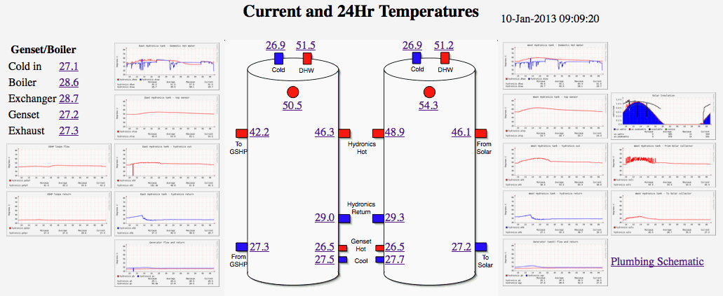
140K BTU = 41KW, so similar size. Mine isn't a gassifier either, but I have an adjustable flap in the front of the ash pan, which lets me control how much air gets in and therefore how quickly the wood burns. Long term, I plan to put a small linear actuator on it (motor and screw) so I have fine grain control over the burn rate, at the moment it's just on/off - burns hard until it gets to temperature, then shuts off. Not ideal! I also plan a thermocouple on the exhaust flue but haven't got there yet.

Webcontrol does "most" of the job for me. It has a few serious limitations from my convenience point of view, I really want clear, on-the-spot display of temperatures and control of setpoints. When I travel and my wife has to operate things, simple, clear readouts are essential. The system manages itself pretty well, but when something out of the ordinary happens, thats when we need to know what's going on, and quickly. I have seperate stand-alone digital temperature readouts, but thats doubling up. I have it on a web page, but its not always convenient.

tanks.gif


Other than that, yes, I'm doing "similarly" to you with the webcontrol boards. I have them distributed around the place where different things are, and with the new webset functionality I hope to make them integrate more tightly. (At the moment I have a central machine running FreeBSD that polls the boards, make some decisions about what's going on in different places, and sends back controls to the different boards)

I would STRONGLY advise you though, before you start cutting code - draw a proper flowchart of what you want to achieve, then code from the flowchart. Annotate the flowchart with labels in your software so you can find where things are later.

I actually write my code in a standard editor, and fully comment it. I then have a one-line command that reads the commented code, strips out the comments and leaves me with straight text to paste into the plc. Without that, it would be almost impossible to maintain any non-trivial code.

Sample of the flowcharts I do for myself when coding: (not usually saved as a gif I might add!)
webctl-tracker-flowchart-16.gif
 
Jim's idea to have a NPN trasistor is a great one. To make sure chip not running at its maximum limit will enlonger its life. We had a customers using TTL output directly drove a printer motor. That seemed working few weeks. Eventually the TTL output chip burned out.

From what your described, It is probably better to have a subroutine to turn on each pump and turn off each pump.
Then you can have three seperate checkings based on air temperature, water temperature, and setpoint temperature to turn the pump on and off.
You can have the safe gaurd routines there always watch over the temperature is too high.

Ross' idea to have a flowchart is important, that way, you can decide where to interlock certain logic to prevent one routine turn it on and the other routine to turn it off. Pumps don't like to be switched on and off too frequent.

In your actual logic, you can take advantage of the bitwise operator to save VAR and RAM. You will need to define what each bit stands for.

We will help you as much as we could, if you have any problem getting it up and running.
 
@CAI_Support. Thanks again. I am starting to see some of the logic in the programming. When I write the subroutine what command branches off to the next logical step? say a subroutine checks for temperature in the boiler, if the temp satisfies I want to implement the next subroutine, if not I want to skip it and go to the next instruction. What makes that happen? Sorry for the basic question!
In the meantime I have implemented the hardware portion using a 5V voltage regulator which is very stable with any input from 8 to 12 volts. Below is the assembled unit, with the board, the voltage regulator and relays. I used an LM7805 and three capacitors.

@Ross, you seem to have the same issue I have with my HS Tarm OT boiler. I have a 4" linear actuator for the door flap, but I think a HD servo works better. For that I sense the temperature in the flu stack, because the water temperature changes too slowly. The fact is, a fan would be better, as the flap really doesnt work that well to resuscitate the fire once is almost out. I am working on that component of the system, as I think it would make a great deal of difference. Thanks for your suggestion: I started a basic flow chart whcih surely makes it easier to analyze the logic flow.

[sharedmedia=gallery:images:521]
 
From what your described, It is probably better to have a subroutine to turn on each pump and turn off each pump.
Then you can have three seperate checkings based on air temperature, water temperature, and setpoint temperature to turn the pump on and off.
You can have the safe gaurd routines there always watch over the temperature is too high.

Ross' idea to have a flowchart is important, that way, you can decide where to interlock certain logic to prevent one routine turn it on and the other routine to turn it off. Pumps don't like to be switched on and off too frequent.

I would like to just raise awareness of a problem I frequently encounter working on other peoples product - and that is the "unexpected consequences" of things that "appear" ok.

For example, in pseudo-code:
start
if time > 9am pump on
if temp1 > 80 pump on
if temp1 < 30 pump off
end

You might think that the pump would be off if the temperature was under 30, but otherwise "on" if it was either after 9am or over 80 degrees

The problem is that the output will be turned on if the time is after 9am, OR if the temperature is over 80 degrees *REGARDLESS*.
It may only be for a short period, but it will still happen.
Why is this a problem? Well, if your output turns on a solid-state relay (especially if it's not one with ZCD for turn-on), the pump will turn ON for at least that half cycle. Some things that have latches may trigger for a minimum run time. Yet when you put a LED on the output, or look at output bit in a browser, the output will "appear" to remain off!

When dealing with real-world outputs, it is far, far safer to just set or clear a flag as your program executes, and at the end of the loop - set the output to the flag state.
This ensures it is only set/cleared at one point and no brief pulses that can be a real PITA to debug.

The same thing can/does apply to subroutines. If your code calls one to turn on a pump, and later it gets called to turn the pump off again, you can easily introduce problem "inconsistent" output states. Just think about what's happening in the real world and keep that in mind when coding.
 
Ross I see the point, especially as far as the real world is concerned... You are basically saying that even if very momentarily, as the code executes things may change state and it is better to collect all the state changes and execute them together at the end of each cycle. Correct?
 
Back
Top