Elk M1 Active Low?

DELInstallations said:
To the OP, either you'd need to invert the rule action (ON is actually OFF, etc.) or use a relay to invert the actual trigger and become a switched negative instead of the switched positive the M1 provides.
 

Sorry, maybe I'm being a bit dense here, but I'm still not certain what exactly I need to connect to terminal 5 on my motion sensor. Would you be able to walk me through it?
 
My M1XOVR can provide a relay (NC or NO), a switched 12V output, or a constant 12V source.
 
I can have the rule rule trigger the relay/output on when either armed or disarmed, makes no difference to me.
 
Thanks!
 
DELInstallations said:
That's not going to satisfy here. Napco is a switched negative/pull to ground. The M1 provides a +V trigger, so the only way would be to invert the trigger, so the trigger would need to be held high in a normal condition and then turn "off" when the desired operation is performed. That's what the Napco manual gets into.
 
I guess I interpret what the manual says differently.
 
Quote: "Status Input*: (Form-A Version only) Panel disarmed, >5V; armed, <1.5V."
 
To me, that doesn't indicate a switched negative design. That's a logic type input, and a pulldown resistor should be able to provide the necessary level just fine.  
 
If you connect the resistor between NEG and an output on the M1, and also connect the output to the status input on the Napco, when the output is on, it will be pulled to +12V, meeting the "armed" condition of >5V.   When the M1's output is off, the resistor will hold the status input to a level close to ground, meeting the <1.5V requirement.
 
If that's not the case, then it is a poorly written spec on Napco's part.
 
If it's of any help, I threw a multimeter on it and I can determine that there's continuity between the + terminal (1) and the status terminal (5)
 
giesen said:
If it's of any help, I threw a multimeter on it and I can determine that there's continuity between the + terminal (1) and the status terminal (5)
 
Well, the Status terminal can't be directly connected to the + terminal, as connecting Status to ground in order to pull it low would create a dead short.  Although your meter might indicate continuity, there is probably a resistor or some other component between the two terminals.
 
giesen said:
So I should connect terminal 5 to the NO terminal and my M1OVR and the COM terminal to a negative power terminal (again on the M1OVR)?
 
Do not connect the 12vdc output of the OVR to the motion detector, I'm afraid it will harm one or both devices.
 
I thought that what you are saying is correct (it is what I said in post #8) but now I'm confused by what DEL and RAL are saying. I thought that you should connect terminal 5 of the motion to NO of the OVR and common to common on the two devices together. Then use Elk rules to turn the OVR output on when the Elk disarms and turn the output off when the Elk arms. Now I see that that is not correct.
 
Your instructions refer to an "arm lug" on the control panel and I didn't know what that term meant so I Googled it. I found a NAPCO Gemini panel instruction manual that describes an arm lug as a terminal that outputs 1vdc when the panel arms and 0.0vdc when the panel disarms. There is no 1vdc output on an Elk panel or OVR so I think that you need to supply this from another source.
 
I THINK that RAL is suggesting using a resistor to reduce the 12vdc output of the Elk OVR to ~1vdc and he can help you better with that.
 
I THINK that DEL is referring to switching a relay with the OVR output and having that relay connected to a 1vdc power supply. I still  don't understand what DEL is saying about a negative signal.
 
It might be easier to use the NAPCO motion detector as an occupancy sensor and buy a separate motion detector for fast response. I like the Bosch Tritech.
 
Mike.
 
 
Can someone explain to me what the motion detector requires to trigger? Is it  ~1volt high and 0 volts low or is it 12 volts high and ~1 volt low? Or something else?
 
Mike.
 
mikefamig said:
Can someone explain to me what the motion detector requires to trigger? Is it  ~1volt high and 0 volts low or is it 12 volts high and ~1 volt low? Or something else?
 
Mike.
Something else.
 
Needs a switched negative, not voltage.
 
If you apply a negative between the terminal and the switched point, you'll read VDC, since you're providing a sink to ground. Turn off the sink, you're going to read 0VDC or minimal. That's what the armed lug is, a switched negative/ground reference.
 
The motion detector terminal is a +V source.
 
The terminology is what's wrong in the documents. When "ON" the unit is a common with the panel's negative. When "OFF" the unit is at a higher reference than the panel's negative.
 
Here's an excerpt from a translated version of a Polish manual for the GEM-OUT8 Active Low Module (I couldn't find an English version of the manual):
 
Module GEM-OUT8 has 8 independent programmable outputs In the normal state, the output potential is positive
(approximately 12V with respect to ground) at the time of activation of the output voltage is reduced to a value of 1-4 VDC at the same time
terms of supply plus there is a voltage 8-11 VDC.

 
So the +12V with respect to ground (when the panel is disarmed) should be pretty easy to accomplish on the M1. How would I achieve the 1VDC?
 
Or am I still completely misunderstanding this?
 
I guess the GEM-OUT8 has been replaced/revised as the GEMC-OUT8. Here's the manual.
 
The GEMC-OUT8 provides 8 "active low" open collector
outputs. Each output will provide a "floating" ground for the
load device. In a normal state, the output will float at
approximately 12VDC relative to ground. When active, the
output will drop to a low state of approximately 1-4VDC,
effectively providing a ground for the load device, which will
then activate. Note: In order to measure or test the state of
an output, a load must be applied to the output. See
Calculating Load Current.

 
Still not sure if this is helpful, but maybe someone can make sense of it.
 
The statement was answered before and the revision is the same verbiage they provided before.
 
Open collector (basically just a leg on a transistor) which is the inverse of the M1's voltage triggers. Normal means it's HIGH in relation to ground and goes low on a trigger. You're not providing voltage to anything, which is evidenced by the 12VDC (host system voltage) reading when the output is HIGH (not pulled to ground) and LOW (~0VDC) when the output is pulled to ground.
 
You would need to sink the output to ground, and in the case of the M1, via a relay, not send voltage into the output.
 
DELInstallations said:
The statement was answered before and the revision is the same verbiage they provided before.
 
Open collector (basically just a leg on a transistor) which is the inverse of the M1's voltage triggers. Normal means it's HIGH in relation to ground and goes low on a trigger. You're not providing voltage to anything, which is evidenced by the 12VDC (host system voltage) reading when the output is HIGH (not pulled to ground) and LOW (~0VDC) when the output is pulled to ground.
 
You would need to sink the output to ground, and in the case of the M1, via a relay, not send voltage into the output.
 
 
Sorry, there seemed to be some disagreement about what it meant, so I just want to verify. In this case I'd wire the COM terminal of my M1XOVR to Elk negative power terminal, and NO terminal of M1OXVR to Status Terminal (5) on the motion detector. Program Elk to activate relay when armed. Or am I missing a step?
 
No. Will not work.
 
You need to provide a sink to ground, so a switched relay that pulls to ground when active. Evident by the statement that you'd read ~12V between that terminal and ground and ~0-4V when pulled to ground.
 
You would need a relay triggered by the M1, then you'd wire the terminal on the motion to the NO and then connect C to the panel ground.
 
The voltage triggers on the XOVR or M1 work the opposite way. They provide voltage and no continuity to ground.
 
DELInstallations said:
No. Will not work.
 
You need to provide a sink to ground, so a switched relay that pulls to ground when active. Evident by the statement that you'd read ~12V between that terminal and ground and ~0-4V when pulled to ground.
 
You would need a relay triggered by the M1, then you'd wire the terminal on the motion to the NO and then connect C to the panel ground.
 
The voltage triggers on the XOVR or M1 work the opposite way. They provide voltage and no continuity to ground.
 
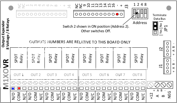
Maybe you're confusing the M1XOVR with something else (maybe the discontinued M1XOV which has 16 voltage ouputs)? The M1XOVR has 8 voltage outputs and 8 relays. What I was suggesting is in the image below. Basically connect the two red points below, and connect the blue point to the status terminal on the motion detector.


The voltage outputs are on top (J3 - flying leads) and the relays are on bottom. I assume the - on the power supply is ground on the M1.
 
giesen said:
Maybe you're confusing the M1XOVR with something else (maybe the discontinued M1XOV which has 16 voltage ouputs)? The M1XOVR has 8 voltage outputs and 8 relays. What I was suggesting is in the image below. Basically connect the two red points below, and connect the blue point to the status terminal on the motion detector.


The voltage outputs are on top (J3 - flying leads) and the relays are on bottom. I assume the - on the power supply is ground on the M1.
 
I would add a wire between the power - on the OVR and the power - on the motion detector as a common reference.
 
mikefamig said:
I would add a wire between the power - on the OVR and the power - on the motion detector as a common reference.
 
The motion detector is already powered by an output on the M1XOVR so should already have a common negative.
 
Back
Top