How to use Elk Relays as speaker switches?

These aren't 32Ohm Elk speakers - the OP said they're audio speakers connected to a Sonos.

I'm concerned that, depending on how that speaker switch works, it could be really screwing up the resistance levels. You really should use a meter to do some testing to find out before you cook your amp!
 
You really should look into something like this

http://www.hacs.com/ab8ss.php


Resistance impedance matching information:

Number of speakers selected= 1 2 3 4 5 6 7 8
Ohm load seen by amplifier= 8.49 4.98 4.13 3.96 4.05 4.27 4.85 4.92
% power to speakers= 94 80 64 50 40 31 29 20
max power internal resistors 10 20 30 40 50 60 70 80
max power speakers 156 80 53 40 33 27 29 20
max power from AMP 166 100 83 80 83 87 98 100


better yet use a setup like mine with multi-amps and control the volume with them as well as have the ability to have true multi-zones.

You can check the nominal DC resistance with an ohm meter that the amp is seeing by switching in and out the relays and see if it is staying between 4 and 16 with all combination's.

This is why I went the route I did as it is hard to control speakers without expensive impedance matching switches that are controllable via IR or RS-232.
 
I suggest reading the owner's manual on the speaker selector and seeing what it says about having unused speaker slots and turning them "on" (which is effectively what he is doing).
 
So effectively your bypassing the impedance matching function of the speaker switch? You can't just remove or add speakers connected to one output without dealing with the impedance being maintained between 4-16 Ohms (in most cases - some amps have a tighter requirement). Not doing so can damage the amplifier.

Good luck and watch for smoke.

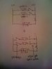
I don' think so. I did the following in the picture - placing 12 relays between the speakers and the selector.

The speaker selector itself is unpowered, so I believe it only "sees" a speaker when there is current going through the speakers, despite the actual position of the push button switch. If this is true, then my relays should just replace the function of the push buttons.

If the relays are in the on position, I complete the circuit through the speaker selector along with impedance matching function. If the relays are in the off position, no current can pass through it because the circuit is broken. So the speaker selector should only "see" the completed circuits, the ones where the relay are on, and perform impedance matching through those.

How can I screw up the resistence levels with this setup? My understanding is that if I accidentally hooked up the speakers in paralle then yes I can drop the resitence, and the more speakers I hooked up in parallel the lower the resitence can drop and blow equipment along the chain. But if the relay switches are open, there'd be no complete circuit, and no chance to accidentally create a parallel circuit?

I looked into the hacs one, but like I said I am a newbie, and getting that unit to work looks like a very daunting task!
 

Attachments

  • Test.jpg
    Test.jpg
    62.5 KB · Views: 36
Your unit might be non powered but I suspect it has resistors built in that are used to maintain the correct impedance. When the switch on the unit turns off a speaker it essentially connects a resistor across the circuit to take the place of the speakers. When you use the relay to open the speaker connection your not using that resistor any longer.

You can do what you want but as someone who has a degree in electronics I am pretty sure you are not maintaining the correct impedance across your amplifier. But this is your setup so do as you want. We are just trying to be helpful.

Thanks! I definitely apprecite the advice. I am not even aware that there is a resister in the push button switch to take place of the speaker. Now I realize someone had suggested this in a previous post. I just had no idea what it meant at the time.

So if I put in a resistor between the NC and COM in the elk relay, it should be similar to the push button switch? Perhaps I can open up the speaker selector, look at the circuit board, and try to figure it out.
 
I took apart the speaker selector.

In the push button ON position, 1/2 and 4/5 are connected. The circuit from the amp to the speakers in the positive terminal is complete.

In the push button OFF position, 3/2 and 6/5 are connected. 3 and 6 doesn't go anywhere.

It looks like the push button switch is just a mechanical switch that completes or breaks the positive terminal connection. There are two resistors on the board rated 50W 3 ohms each, one for each channel. It goes from + from amp => resistor => + to 6 different speakers in parallel.
 

Attachments

  • photo.jpg
    photo.jpg
    81.3 KB · Views: 18
I believe this is how I wired the elk relays. The top is the original circuit for one channel, and there are two of these circuits on the board - one for left and one for right. The bottom is what I believe is my modified circuit after introducing the elk relays.

I think it looks safe?

Pardon the picture, it's just simplier to draw and my scanner is down so I had to take a picture.
 

Attachments

  • photo2.jpg
    photo2.jpg
    99.8 KB · Views: 25
Galun,

If I were you I'd be a bit concerned - there's a whole lot of people here trying to explain to you that just throwing a cutoff switch after the speaker selector *probably* isn't doing exactly what you want it to... but for whatever reason, we're just not able to make it clear enough. As JWilson said - this is your setup - do as you wish with it... but you've got people with a lot of experience in these matters trying to help clarify the complexities in what you're doing (that's why you posted here isn't it?). What you're after is perfectly doable - but there's a right and a wrong way of doing it. It's not even that complex - to finish this out correctly you're proubably only talking about $2 worth of resistors and a little bit of time to hook them up to the relays.

I really suggest you get yourself a decent electrical meter if you don't already have one - set it to Ohms measurement and disconnect where the speakers hook into the amp (otherwise the amp will interfere with the test) - and hook one lead up to each speaker wire. With all the speakers on you should see somewhere between 4 and 8 ohms. Now turn your relays on one by one and watch what it does to your resistance. In fact - report back your findings and we'll help you interpret them.

What you seem to be missing is that the switch is not just interupting the circuit - it's most likely diverting the circuit to a resisted load to take the place of what the speaker would be doing to the load when connected. What you're doing is just interupting it - which will most likely have adverse effects on volume level and impedance. You amp may seem OK for a bit - but push it the wrong way and it's either going to blow the internal protection circuit or just blow the thing altogether.

We're all just trying to help here - read back and we're all saying the same thing over and over.

How about also posting the make and model of your speaker selector and maybe we can google it to see if there are any better specifics about it available online?

Thanks very much for all the offer to help. I think my written words on the forum may have protrayed my wrong intentions. I am definitely humbly asking for help, and if my posts appear to be stubborn and saying the same thing over and over again, I tihnk it's really just a function of my relative lack of knowledge and my ignorance. I did not know where I went wrong and along the way I leaern more and more as more experts post.

Work2Play, thanks for teaching me how to test. Turns out I am definitely bypassing the impedance matching function of the speaker selector with the relays. I have 6 rooms total - 2 rooms with 2 speakers in each room and 4 rooms one speaker in each room. The speakers are from monoprice. http://www.monoprice.com/products/product.asp?c_id=108&cp_id=10837&cs_id=1083702&p_id=4619&seq=1&format=2

With the amplifier unhooked from the speaker selector, turning individual zones on present 4 ohms (the 2 rooms with 2 speakers) to 8 ohms (4 rooms with one speaker. When I turn on multiple relays, the resistence go down as if the speakers are hooked up in parallel. When I turn on relay 1 with one 8 ohm speaker, the resistance measures 8 ohms. When I turn on relay 1 and 2 with one 8 ohm speaker at each relay, the resitance measures 4 ohms. When I turn on relay 1 and relay 3, relay 1 with 8 ohms (room with one speaker) and relay 3 with 4 ohms normally (the room with 2 speakers), the resistance measures 2.8 ohms or so, as if I have 3 speakers wired in parallel.

If the impedance matching is working, the resistance reading for all of them should be the same regardless of which or how many relays are turned on?

The speaker selector is a Sima SSW-6. http://www.simaproducts.com/products/product_detail.php?product_id=47

So... what do I do next?

Thanks!
 
I did some searching and came across a diagram for an eight way speaker switch. If you follow it and replace the switches with double pole double throw relays you could essentially do the same thing.

http://docs.google.com/viewer?a=v&q=cache:iNvBEKplMEcJ:www.mcmelectronics.com/content/ProductData/Manuals/50-6225.pdf+schematic+for+speaker+selector+switch+eight&hl=en&gl=us&pid=bl&srcid=ADGEESicS4QaWNhuA0GCLTxxBCp6pxBp57GLDNK9Ov8pWUAZ3sCVT2ohBmItCeJbrKOHT4e2PbO0DY5h4RSGUW4_965tet92MQ3I4Z07RuIckW3bpy_-AYE-THCHcdn_yj3tc3ZhSJW6&sig=AHIEtbTrm0vys1l0lp815BTMoB0KVBS3eA

As you will see it is not a simple diagram. This is because it switches the speakers around (series and parallel) combined with a couple resistors to maintain the impedance between 6-18 ohms. I am sure if you take your current switch apart you will find something like it.

So the short answer for me is this is not the way to go. Your sound quality will suffer and most likely the volume levels at each location will be inconstant with no way to control them individually. I know that most people want to start off simple but in the end by the time you realize that you will want some way to control the volume in each room and start adding LPADS you total costs will climb. Read my blog and you will see I started down that path and quickly changed my mind.
 
I did some searching and came across a diagram for an eight way speaker switch. If you follow it and replace the switches with double pole double throw relays you could essentially do the same thing.

http://docs.google.com/viewer?a=v&q=cache:iNvBEKplMEcJ:www.mcmelectronics.com/content/ProductData/Manuals/50-6225.pdf+schematic+for+speaker+selector+switch+eight&hl=en&gl=us&pid=bl&srcid=ADGEESicS4QaWNhuA0GCLTxxBCp6pxBp57GLDNK9Ov8pWUAZ3sCVT2ohBmItCeJbrKOHT4e2PbO0DY5h4RSGUW4_965tet92MQ3I4Z07RuIckW3bpy_-AYE-THCHcdn_yj3tc3ZhSJW6&sig=AHIEtbTrm0vys1l0lp815BTMoB0KVBS3eA

YES! Thanks! Looking at the diagram in page 3, it does look very similar to the circuit board of my speaker selector when I took it apart.

I observed 1 ohm of resistance when I turned all relays on. That makes sense as I have 8x 8 oohm speakers wired in parallel, so 1/((1/8)x8)=1. Humm... why haven't I blown my equipment?

The explanation on page 3 is tremendously helpful in helping me think about how the speaker selector works. I am going to map out the circuit board tonight and trace what resistance the amplifier is seeing when I turn on/off the relay/push button switches, then reconcile them to my actual observations. Then perhaps I can introduce resistors into my circuit to make sure the amplifer never sees anything below 4 ohms.
 
Thanks very much for all the offer to help. I think my written words on the forum may have protrayed my wrong intentions. I am definitely humbly asking for help, and if my posts appear to be stubborn and saying the same thing over and over again, I tihnk it's really just a function of my relative lack of knowledge and my ignorance. I did not know where I went wrong and along the way I leaern more and more as more experts post.
No worries man - glad we're makin' progress - it seems you now understand what's going on a lot better... when in doubt, of course feel free to ask for tips - from how to test, etc... this is a pretty helpful and kind forum - not like some others I've been around where everyone's answer is "RTFM" or "Use the search!".

I'm working now but I'll be curious to scan through the specs and that document from jwilson - I expect that'll be pretty helpful for us all to understand better what's really going on inside that switch. I knew it was something complex because of how speakers work; but wasn't sure exactly.

I'm not ready to say you're going down the wrong path yet - at this point it comes down to what you have more of - time or money... If you've got time to kill and want to keep it on the cheap I suspect that'll still be perfectly doable (the remaining parts you'll need are extremely cheap). And if you get sick of it down the road, you can always change it up later. As jwilson mentioned - you may see volume spikes and all - but it shouldn't be any different then pressing the buttons on the switch today - so if you're ok with that performance then you should be fine.

As for the amp - well, I'd imagine you haven't pushed it too hard yet; and amps are just made differently... but 1Ohm isn't good for any amp you'd be using at home.
 
It appears that some of the speaker selector switches that claim impedance matching or amp protection just put a small, high power resistor in series with each channel (left and right) to limit how low the resistance that the amp sees can go. With a 3 ohm resistor in series and from 1 to 8 pairs of 8 ohm speakers the resistance (actually impedance...) would vary from 11 ohms for one speaker (8+3) to 4 ohms for all 8 (3+8/8). That seems pretty good and is a lot less complicated than the series/parallel switching for the other unit posted. If you want to have a minimum of 8 ohms just use 7 ohms for the added resistance. Max would be 15 ohms. If you want to allow all speakers to be open put an 8 ohm resistor in place of one set of speakers.

The down side is not being able to adjust the individual levels, the heat generated in the resistors at high volume levels, and limiting the power delivered to much less than the amp output (when all the speakers are on). The sound output will also vary with how many speakers are on. But it is simple and cheap so if you can live with the limitations it may work fine for you.
 
Having the Elk should make this pretty easy. I would run two banks of three relays for each channel for a 6 pair setup (12 relays total needed). Put the two banks in parrellel and the three speakers in each bank in series. Use the NO side for the speaker and the NC side for the resister so turning the relay on would turn the speaker on. With 8 ohm speakers on the NO side and 8 ohm resisters on the NC side of the relay then your impedence would be 12 ohms altogether.

In other words you would always have 24 ohms of resistance on each bank of three (8 times 3) and then by running that in parrellel with the other bank of 3 (also at 24 ohms), it drops to 12ohms total. Doing it this way will also mean that the resistance that the amp sees will be constant regardless of what speakers are on and therefore you won't get volume level changes when you turn speakers on or off.

The only possible side effect of this is that there might be a little "click" when you turn speakers on and off since for a microsecond the relay will be traveling from open to closed losing output to the other speakers on that series of three and upping the resistance on the other bank of 3 to 24ohms. I suspect, however, that it will happen so fast that you won't hear it.

One note, if you used dpdt relay you could do it with 6 relays. Elkm1rb is only a spdt.
 
Back
Top