You are using an out of date browser. It may not display this or other websites correctly.
You should upgrade or use an alternative browser.
You should upgrade or use an alternative browser.
Reversable Motor with WC8, DPDT and STSP relays
- Thread starter rfeyer
- Start date
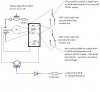
I assume, know what they say about assume, the motor is reversible. The extra wires may be limit switches detecting end of travel or perhaps speed control, but my bet is end of travel detection.
Here are some more sources for motors. All Electronics has automotive window motors so it may help figuring out how to connect it:
http://www.allelectronics.com/
http://www.surpluscenter.com/
http://www.mpja.com/
Good luck solving how to hook up the "mystery" motor.
/tom
Here are some more sources for motors. All Electronics has automotive window motors so it may help figuring out how to connect it:
http://www.allelectronics.com/
http://www.surpluscenter.com/
http://www.mpja.com/
Good luck solving how to hook up the "mystery" motor.
/tom
")
You are right, assuming is what I did - I mean, a windshield motor should go up and down, right?
TY for the links - I will get another motor but also keep looking for answers on the motor I have for other uses. So far I found out it has a Hall Effect Sensor, which then would go along with the limiter/ speed functions, and, limiting functions would be great to have built in
Trying to figure out how to use the 'pulse' information may be a task for someone much smarter than me, but I will play since I have 2 of them and if I loose one, well, for a good cause!Rainer
rfeyer said:You are right, assuming is what I did - I mean, a windshield motor should go up and down, right?
It's been decades since I've used windscreen motors, and they've probably changed in that time.
Back then, they used to have one wire for "low" speed, one for "high" speed, one that had power permanently applied, and ground.
They had a contact that opened when the motor was in its "home" position, which was used for auto-parking - if you turned the wipers off when they were anywhere except in the proper place, they'd keep going until they were back home.
Also, windscreen motors only turn one way - the backwards and forwards motion is created by the mechanical linkages.
That certainly makes sense, yup, I have seen the linkage in wipers and actually used the principle when I had salt water fish tanks - made my own oscillating water pumps for flow (and knew nothing about electroncs then either )
There is a guy at Allelectronics who made a review and stated that his students took one apart, that is how he knew that it is a Hall type sensor. I left a message hoping he could give the circuit, but we'll see.
TY for the info. I did order another motor written up as REVERSABLE. One way your and /toms suggestions will become active
Rainer
)There is a guy at Allelectronics who made a review and stated that his students took one apart, that is how he knew that it is a Hall type sensor. I left a message hoping he could give the circuit, but we'll see.
TY for the info. I did order another motor written up as REVERSABLE. One way your and /toms suggestions will become active
Rainer
rfeyer said:I did order another motor written up as REVERSABLE. One way your and /toms suggestions will become active
A couple of telltale signs.
DC Motors described as "brushless" are almost always electronically commutated. (ECM), and are rarely reversable by simply swapping polarity.
DC Motors with brushes of any form are usually simple electromechanical devices that will run forwards or reverse in the way you want.
Many low-speed motors are merely an integrated motor+gearbox.
Old battery drills and/or screwdrivers used to be a good source of suitable motors, and were frequently available by the dozen for free.
I've search high and low for any description which says it is or is not brushless, found nothing.
Did think about an old 9.6v cordless drill, but couldn't figure out how to hack the speed adjustment. Plus, I really like picking everyones brain for info and learn something
Rainer
Did think about an old 9.6v cordless drill, but couldn't figure out how to hack the speed adjustment. Plus, I really like picking everyones brain for info and learn something
Rainer
OK, lets see if I learned anything at all!
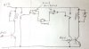
I came up with the below RUDimentary diagram looking at all choices, including tons from other sources, and my own attempt to apply my very limited comprehension of electronics.
Please let me know if it makes any sense at all.
I thought it would make sense to use Transistors rather than additional relays to eliminate the problem with VDC source.
Also, I am still unclear why the coil of the transistor can not be used as a way to change direction of the motor. I am pretty sure I must be missing something in the logic, so I am hoping for corrections from you all.
Rainer
Attachments
CAI_Support
Senior Member
You supposedly use two relays, one controlled by one TTL output, in that way, one for turning one direction, another TTL output will turn on reverse direction. Please make sure when WC lost power, the motor stops. That can be accomplished when no TTL input, both sides of the motor stay both high or both low. Ensure it works correctly, then connect the load to motor. You may also have certain travel limit switch so that it will not break whatever you are driving.
In your diagram, as presented, the NPN transistors won't operate "high-side" as you have drawn.
The extra diode in series with the "on/off" transistor is reverse-biased and would prevent the motor running.
The diode across the relay coil is permanently forward-biased and will blow up (or blow the transistor) as soon as you operate the reversing relay
The limit switches are difficult for me to understand which is where, but seem to require a lot of unnecessary additional cabling from motor site back to the control site.
The usual method is two limit switches, both normally closed, in series, each bypassed by a diode (in opposite directions) such that a closed limit switch will prevent the motor driving further into the limit switch, but will permit the motor to run in the opposite direction.
Finally, you were suggesting your motor could take 5A.
The NPN transistor you have indicated as the stop/start control in your diagram will need to be a darlington, and will need to be mounted on a decent heatsink, with that sort of current, it will get very hot very quickly without one.
Ty. Rossw!
I will try to figure out why I made the mistakes, then try to understsnd the drawingl which I am sure makes more sencemthan mine,
do you believe it would be best to use spdt relays insteadnofnthe transistors? I do ave two TIP120s which I bought for another plan.
rainer
I will try to figure out why I made the mistakes, then try to understsnd the drawingl which I am sure makes more sencemthan mine,
do you believe it would be best to use spdt relays insteadnofnthe transistors? I do ave two TIP120s which I bought for another plan.
rainer
Similar threads
- Replies
- 12
- Views
- 9K