rfeyer said:do you believe it would be best to use spdt relays insteadnofnthe transistors? I do ave two TIP120s which I bought for another plan.
The TIP120 has an Hfe of 1000, so it has enough gain to do the job.
Maximum collector current is only 5A. If your motor takes 5A running, it will probably need more to start, and this transistor is already right at its limit.
It would work, but it really is pushing it.
I like the simplicity of two SPDT relays. It gives a whole slew of benefits over the more complex arrangement with a DPDT. It is also intrinsically "safer" in the event of a failure of the WC, because if both outputs are on OR off, the motor is off. It uses cheaper, more readily available relays, and if you use the inexpensive relay-driver boards, it is an "over-the-counter" replacement.
Where the DPDT relay for direction reversal, along with a series transistor or FET really comes into its own, is where you are using PWM for speed control.
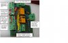
I do this on my tracker controller - fragment of the schematic produced below. It's more complex than you need, but quick explanation of some salient points. D1 is the diode across the relay. The IRLZ14 is a logic-level power FET that is operated at several KHz to control the speed of the actuator from zero to full speed. D2 is across the actuator (motor), because without a relay to disconnect it, the back-EMF would destroy other parts. R6 is a current-sense resistor, amplified by U2d, to provide feedback about the actuator current, it lets me detect high wind load, jammed actuator, etc.
In your case, the WC doesn't have PWM out and I really doubt the extra complexity is justified in the application.