mantamania
Member
Hi !
I am intrested in 2-3 pcs. depending on the price, and of cource if you will send to sweden !
I am intrested in 2-3 pcs. depending on the price, and of cource if you will send to sweden !
It will substantially increase the size of the board, and adds a lot of extra complexity simply because there are so many ways people may want to use it. For example:Maybe for Revision 2.0, but here are some ideas for your expansion board:
-Add opto-coupler for all 8 logical inputs
This board doesn't currently connect to the output connectors.-Add small SSR as output protection: PVT312
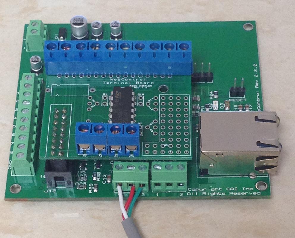
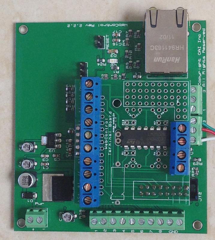
Again, depends on the system configuration. There is the prototyping area down the side, which could easily take a number of additional screw terminals, and a wire run down the back can easily connect them to the 0V rail (already right there).-one ground 0V connection point is maybe too few for 8 inputs ?
I'm happy to ship to Sweden. As for price - well, the boards are being made now. Do you want just bare boards, or do you want them populated?I am intrested in 2-3 pcs. depending on the price, and of cource if you will send to sweden !
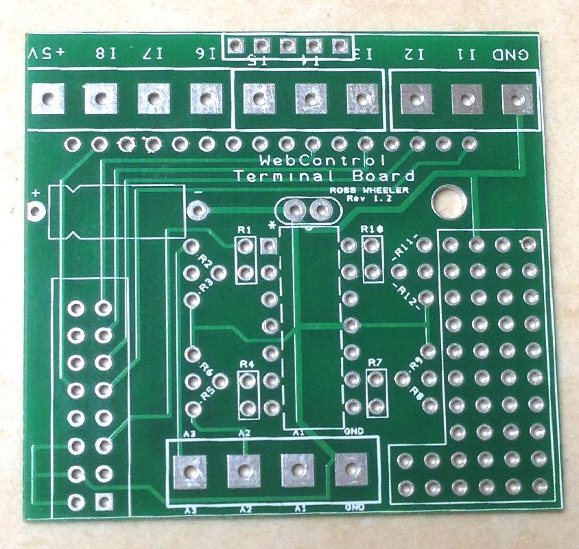
is the spacing of the input resistors 1 4 7 such that one could put a jumper there instead if someone doesn't need the input filtering? Of course the cost is that big a deal I guess
what's the PCB gonna cost?
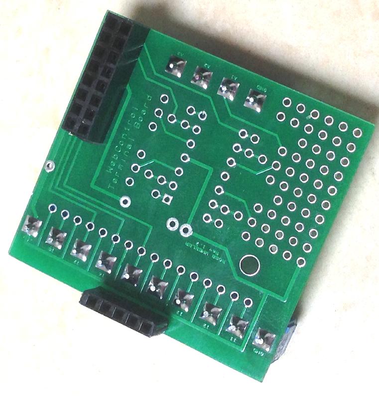
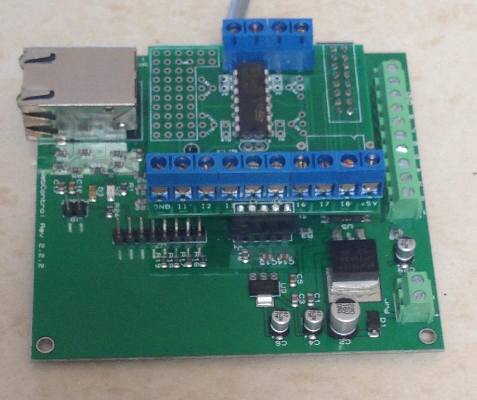
Hah. I got green so it would match the WebControl board!it looks great! Next time get it in red LOL
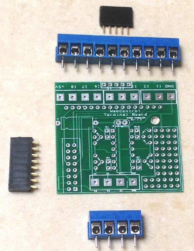
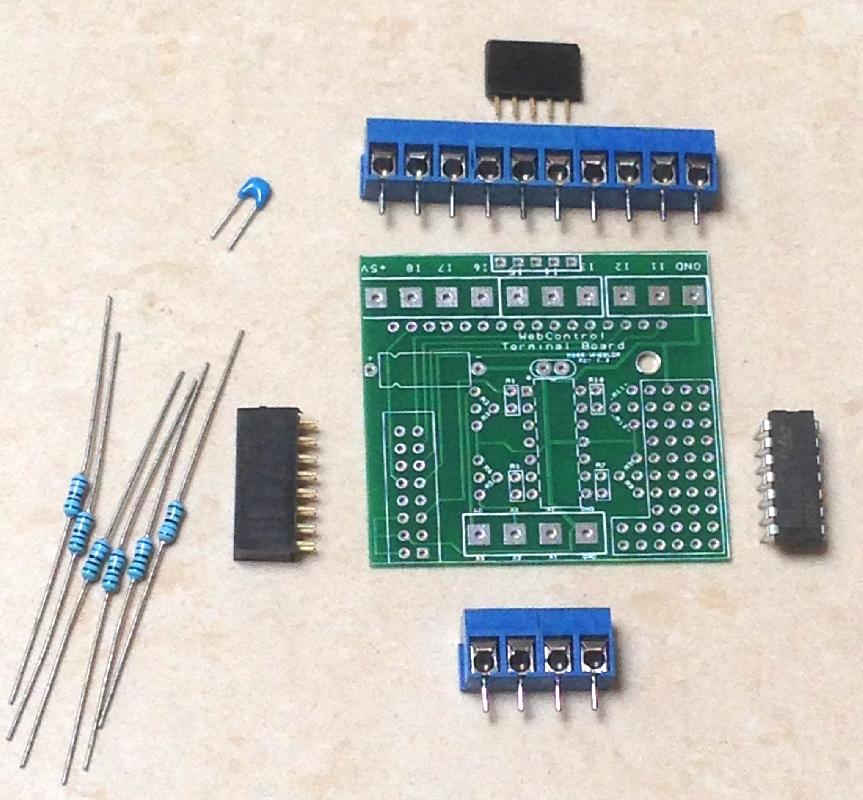
well you could sell it as a kit as long as you tell us where the different resistors go. I have no problem soldering it myself but I'm sure someone here would like a complete one.
")
That amp is similar to the circuit in the Kill-a-watt meter, which amplify an AC voltage drop on a short copper loop wire. AC signal can be easily amplified to a bigger signal. Even Ross' design is for DC circuit, it can be easily modified to measure grid-tie inverter output also.