Mantamania, calculating gain is actually fairly straightforward.
Firstly, identify what your input voltage range will be. Example, 0-1V
Secondly, work out what voltage range you want to offer to the WC A/D input. For maximum useful range, you want 0-10V
The gain you require is (in this case) +10 (10-0) / (1-0) = 10/1 = 10.
If you want a non-inverting amplifier (as in this case), per the notes on my schematic:
In this configuration, the gain is simply 1+(R1/R3)
So we want R1/R3 to be 9. I like to use "middle-of-the-road" resistors, not so high noise is a problem, and not so low current is a problem.
Using standard resistor values, 30K for R1 and 3K3 for R2 gives a gain of 1+(9.0909) = 10.09.
This is probably "close enough" for the majority of cases. (Adding a 33R in series with the 3K3 would make the gain 10.0009)
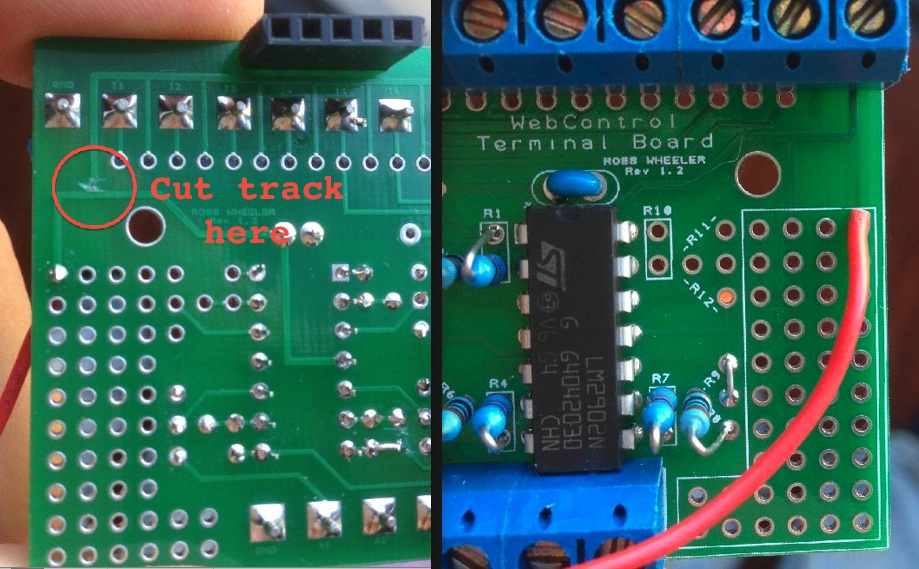
The only remaining problem is that as the terminal board is intended to run off the WC boards internal 5V supply, it will never reach the 10V output and will clip. I considered this in the design, and it's fairly simple to cut one track and run the board from another supply - in my case, I am running the webcontrol board from a 12V regulated supply, so I simply use that.
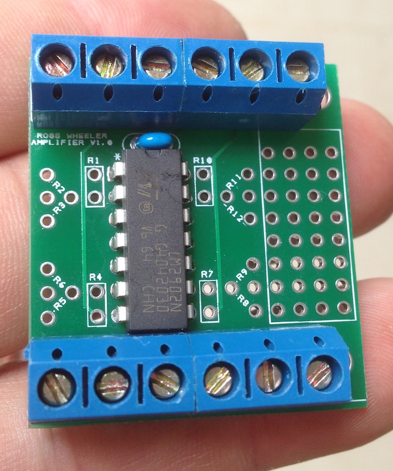
Here's a photo showing the mod:
Making the mod is fairly easy. Take a sharp knife (razor blade, scalpel etc), cut across the track about 2mm wide. Place a hot soldering iron on the cut section, allow it to get hot. While gently pressing down onto the track with the iron, slide the iron and track out cleanly. You will feel when it "lets go". Of course, you can use a dremel if you prefer, but this method is quick, clean and easy.

")