You are using an out of date browser. It may not display this or other websites correctly.
You should upgrade or use an alternative browser.
You should upgrade or use an alternative browser.
2 CO detectors, not same voltage reading in ElkRP
- Thread starter jsp
- Start date
How did you connect them to the panel, and where (at what point) are you taking the voltage measurements?
Reading is in ElkRP status window, I guess this must be input voltage.
Their connect to their own zones and to the VAUX power.
BraveSirRobbin
Moderator
Are you using EOL resistors? Where are they located and how did you wire them into the system?
Are you using EOL resistors? Where are they located and how did you wire them into the system?
The detectors are CO8RD and has the following contacts: COM,NO,NC,GND,12V,24V
EOLR installed on NC and NO contacts
COM to NEG on panel
NO to Zone on panel
Power connect to GND and 12V going to panel VAUX power
Here is the device spec sheet:
http://www.nadi.com/section2_co_gas_specs/CO8RD_CDN_spec.pdf
BraveSirRobbin
Moderator
The detectors are CO8RD and has the following contacts: COM,NO,NC,GND,12V,24V
EOLR installed on NC and NO contacts
COM to NEG on panel
NO to Zone on panel
Power connect to GND and 12V going to panel VAUX power
Here is the device spec sheet:
http://www.nadi.com/...RD_CDN_spec.pdf
Your EOL resistor isn't completing a circuit connected to the NC and NO contacts of that sensor. The relay on the sensor uses EITHER the NO and Common (for Normally Open circuits) OR NC and Comman (for Normally Closed circuits).
Also, the EOL needs to be in 'series' with the circuit.
Your EOL resistor isn't completing a circuit connected to the NC and NO contacts of that sensor. The relay on the sensor uses EITHER the NO and Common (for Normally Open circuits) OR NC and Comman (for Normally Closed circuits).
Also, the EOL needs to be in 'series' with the circuit.
Would I have to connect the EOLR to the COM and NO contacts and leave the NC alone ?
I am also wondering why one zone would receive 7.2V while the other one 4V.
BraveSirRobbin
Moderator
Doing a quick search it appears the best way to wire this would be to use a normally open circuit with the EOL resistor installed in the NO and COMMON terminals of the CO sensor.
I would first make sure you have no wiring problems as I'm nervous about the fact that you have similar sensors wired and set up the same with different results. Do you have a multi-meter to test your cabling?
I would first make sure you have no wiring problems as I'm nervous about the fact that you have similar sensors wired and set up the same with different results. Do you have a multi-meter to test your cabling?
Doing a quick search it appears the best way to wire this would be to use a normally open circuit with the EOL resistor installed in the NO and COMMON terminals of the CO sensor.
I would first make sure you have no wiring problems as I'm nervous about the fact that you have similar sensors wired and set up the same with different results. Do you have a multi-meter to test your cabling?
Ok thanks, I didn't find much information with my searches. Unfortunately no multi meter at hand, I will get one if I need to (I know I should have tested all wires before starting, but I got all excited and started anyway)
Looking at the other thread I found the EOLR FAQ, I will read through that one, maybe it will clarify some things up.
Lagerhead
Active Member
Actually this is exactly how I have wired mine (!). Putting the EOL resistor across the NO and NC contacts is a convenience, because it lets you avoid a flying splice connection. The relay when deactivated (non-alarm) has the resistor in series with the zone (because COM=NC) exactly as if ir were discretely wired in the circuit in series. It certainly works -- has worked here for years. I can't think of a reason not to do it this way. Maybe it is even a little bit better in "keeping an eye on the relay?"EOLR installed on NC and NO contacts
COM to NEG on panel
NO to Zone on panel
Power connect to GND and 12V going to panel VAUX power
So unless jsp's low-reading relay is faulty, it would seem that there is some issue with the wiring, poor electrical contact somewhere, wrong resistor value, etc. etc.
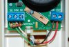
Attachments
BraveSirRobbin
Moderator
Putting the EOL resistor across the NO and NC contacts is a convenience, because it lets you avoid a flying splice connection. The relay when deactivated (non-alarm) has the resistor in series with the zone (because COM=NC) exactly as if ir were discretely wired in the circuit in series.
Wow, I never thought of that, but you are correct! I initially pictured the other end of the resistor just hanging out in the open when I first replied. Thanks for pointing out my mistake as I obviously should have thought about this some more! :blush:
Actually this is exactly how I have wired mine (!). Putting the EOL resistor across the NO and NC contacts is a convenience, because it lets you avoid a flying splice connection. The relay when deactivated (non-alarm) has the resistor in series with the zone (because COM=NC) exactly as if ir were discretely wired in the circuit in series. It certainly works -- has worked here for years. I can't think of a reason not to do it this way. Maybe it is even a little bit better in "keeping an eye on the relay?"
So unless jsp's low-reading relay is faulty, it would seem that there is some issue with the wiring, poor electrical contact somewhere, wrong resistor value, etc. etc.
Wow, I never thought of that, but you are correct! I initially pictured the other end of the resistor just hanging out in the open when I first replied. Thanks for pointing out my mistake as I obviously should have thought about this some more! :blush:
Ok, now that we know this is connected properly, I will go and verify the connections on the CO detector that reads 4V on the panel, just to make sure it is correct. If connections aren't the problem, you were suggesting I should check the wiring with a volt meter, I will try to borrow one from a friend or buy one off the electronics store here. How should I go about testing the wires?
BraveSirRobbin
Moderator
Your 4V value suggests that you're possibly seeing 2 resistors in series, basically a high resistance fault showing.
CO's should always be wired as a NO circuit with the EOLR across the circuit at the last device. That's how the panels expect them, just like a fire alarm. Also, if the unit has trouble relay contacts, they should be wired in series with the circuit to remove the EOLR so the panel recognizes a trouble.
CO's should always be wired as a NO circuit with the EOLR across the circuit at the last device. That's how the panels expect them, just like a fire alarm. Also, if the unit has trouble relay contacts, they should be wired in series with the circuit to remove the EOLR so the panel recognizes a trouble.
Your 4V value suggests that you're possibly seeing 2 resistors in series, basically a high resistance fault showing.
CO's should always be wired as a NO circuit with the EOLR across the circuit at the last device. That's how the panels expect them, just like a fire alarm. Also, if the unit has trouble relay contacts, they should be wired in series with the circuit to remove the EOLR so the panel recognizes a trouble.
This was a close assumption. I installed the wrong resistance. I got a multi meter and reading the resistance on the circuit output 0.8 Kohm. I didn't noticed but some were included with the ELK panel for the 2-wire smoke detectors, I guess this is why 4V didn't go into alarm status too.
Thanks all for your help, I have learned from this thread.
Similar threads
- Replies
- 11
- Views
- 1K
- Replies
- 4
- Views
- 653