SteveInNorCal
Active Member
The ELK-M1TWA (Two Way Amp for Listen-in) draws 15 mA nominal in standby, but 1,000 mA (1 Amp) maximum during listen-in and announcements.
I want to power it off my Altronix 2.5A auxiliary power supply rather than the Elk M1G.
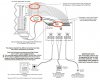
The TWA circuit board has a terminal block to connect it to an aux power supply. BUT...what do I do about the power being fed to it via the J16 jack on the Elk M1? (it connects to J4 on the TWA). The red and black wires on the 12-wire cable from J16 to J4 are +12VDC and NEG respectively.
Should I cut the red and black wires? Or leave them alone?
Maybe the presence of +12VDC on the terminal block automatically causes the unit to switch off the +12VDC on J4 red and black?
I sure wish Elk did a better job addressing all the niggling installation and wiring details in their docs.
Any help much appreciated! I'm trying to wrap up this installation and this is one of the last details.
Steve
I want to power it off my Altronix 2.5A auxiliary power supply rather than the Elk M1G.
The TWA circuit board has a terminal block to connect it to an aux power supply. BUT...what do I do about the power being fed to it via the J16 jack on the Elk M1? (it connects to J4 on the TWA). The red and black wires on the 12-wire cable from J16 to J4 are +12VDC and NEG respectively.
Should I cut the red and black wires? Or leave them alone?
Maybe the presence of +12VDC on the terminal block automatically causes the unit to switch off the +12VDC on J4 red and black?
I sure wish Elk did a better job addressing all the niggling installation and wiring details in their docs.
Any help much appreciated! I'm trying to wrap up this installation and this is one of the last details.
Steve