Hi there,
if anynone wants to build a GTI LIMITER or need to shift load around - - the accuracy with 1000 watt inverter should be about =/-4 watt as itt is 256 steps . use it to shift load around say when one GTI inverter is over producing it shifts load to another GTI as for most GTI the max might be listed as one number but it is better to run them at 80% of max output... or if you live in an area that does not allow roll back of power meters. this will adjust the power out put of your GTI to out put to match your meter.. the code might be still a little buggy but is working well for my purpose. I will post updates to sketch as I improve it - if you use this --- please post back any modification you made for other people to benifit -- Thank you
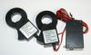
there are a couple ways of building it you could use 3 -SCT-013-000, but i choose to use 1 and 1 ted MTU. as it is much easier to build that way.. as 3 SCT-013-000 had a significant delay
parts:
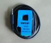
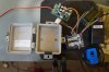
1 TED MTU $20 and up on ebay
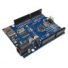
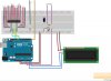
1 - Arduino $5 on ebay
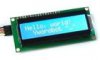
1 - I2C LCD $5 on ebay
1- ad5206 digital pot (100k) $8 digikey
1-SCT-013-000 (100amp) $8 on ebay
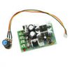
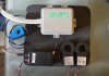
6 - 20 amp DC10-60v PVM $7 on ebay ( or bigger ones thes on are the right voltage at the pot 5v- other ones ar 7 volt
- but you can step down with an led or a resistors)
1-33ohm resistors
2-10k resisters
1- 10uf cap
reference:
http://www.homautomation.org/2013/09/17/current-monitoring-with-non-invasive-sensor-and-arduino/
https://www.arduino.cc/en/Tutorial/DigitalPotControl
http://cocoontech.com/forums/topic/25589-very-cheap-ted-1001-house-power-monitors-and-possible-hacking/page-6
modify the mtu - one wire to ground and one wire to pin one on TDA5051A rx out - i used the a trace from pin one and used a open spot near the chip scatch it clean and attached it there as it is also the ground for digital RX/TX for the chip
here is my sketch based on one 1 - SCT-013-000 and 1 - ted MTU basically connect the ted as normal to your fuse panel and put the SCT-013-000 on the lin in from your solar equipment GTI if yo have more then one GTI going to multiple fuses then hopefully it is on a sub panel then you just hook it one to one of the lines coming from subpanel to the main fuse box..
#include <stdio.h>
#include <Wire.h>
#include <LiquidCrystal_I2C.h>
#include <SPI.h>
#include <EmonLib.h>
// Set the LCD address to 0x27 for a 16 chars and 2 line display
LiquidCrystal_I2C lcd(0x27, 16, 2);
const byte numBytes = 32;
const int slaveSelectPin = 10;
EnergyMonitor emon1;
byte receivedBytes[numBytes];
byte numReceived = 0;
int cnt = 0;
float kw = 0;
float volts = 124;
float stp = 255;
float levelper = 100; // percentage of step for pot
float invpb = 100; // inverter probable max output
float inv2 = 100; // inverter calulation value
float inv3 = 100; // inverter calculation value
float diff = 100; // pot comparison diff
float level1 = 100; // post level calculation
float inverter = 1;
float kw1 =0;
float le=127; // level saved condition
int rl1=127; // rlevel saved condtion
int level=127; // main pot control for PWM
int rlevel=127; // if you need reverse pot direction of PWM
boolean newData = false;
void setup() {
Serial.begin(1200);
Serial.println("<Arduino is ready>");
Serial.println(level);
// Serial.begin(1200);
lcd.begin();
pinMode(slaveSelectPin, OUTPUT);
SPI.begin();
//emon1.voltage(2, 234.26, 1.7);
// Voltage:input pin, calibration,phase_shift
emon1.current(1, 111.1);
// Current: input pin, calibration.
}
void loop() {
recvBytesWithStartEndMarkers();
showNewData();
// output();
// potset();
}
void recvBytesWithStartEndMarkers() {
static boolean recvInProgress = false;
static byte ndx = 0;
byte startMarker = 0xAA;
byte endMarker = 0xAA;
byte rb;
while (Serial.available() > 0 && newData == false) {
rb = Serial.read();
if (recvInProgress == true) {
if (rb != endMarker) {
receivedBytes[ndx] = rb;
ndx++;
cnt = ndx;
if (ndx >= numBytes) {
ndx = numBytes - 1;
}
}
else {
receivedBytes[ndx] = '\0'; // terminate the string
recvInProgress = false;
numReceived = ndx; // save the number for use when printing
ndx = 0;
newData = true;
}
}
else if (rb == startMarker) {
recvInProgress = true;
}
}
}
void showNewData() {
if (newData == true) {
Serial.print("This just in ... ");
for (byte n = 0; n < numReceived; n++) {
Serial.print(receivedBytes[n], HEX);
Serial.print(' ');
}
Serial.println();
showGroupsOfBytes();
newData = false;
}
}
void showGroupsOfBytes() {
if ( receivedBytes[0]==0x4E ) { // change this to match your MTU it - it will display in serial print
if (cnt == 10) {
byte j = ~receivedBytes[6];
byte k = ~receivedBytes[7];
byte m = ~receivedBytes[3];
byte r = ~receivedBytes[4];
double voltage = 0;
double power = 0;
voltage = ( k<< 8) | j;
voltage= (123.6 + (voltage - 27620) / 85 * 0.4);
volts=voltage;
power = (r<<8) + m;
power = 1.19 + 0.84 * ((power - 288) / 204);
kw = power;
lcd.clear();
lcd.setCursor(0,0);
lcd.print("volts ");
lcd.print(voltage);
lcd.setCursor(1,1);
lcd.print("kw ");
lcd.print(power);
}
}
cnt = 0;
double Irms = emon1.calcIrms(1480); // Calculate Irms only
/* emon1.calcVI(20,2000);
// Calculate all. No.of half wavelengths (crossings), time-out
emon1.serialprint();
// Print out all variables (realpower, apparent power,
// Vrms,Irms, power factor)
//float realPower = emon1.realPower;
//extract Real Power into variable
// float apparentPower = emon1.apparentPower;
//extract Apparent Power into variable
//float powerFActor = emon1.powerFactor;
//extract Power Factor into Variable
float supplyVoltage = emon1.Vrms;
//extract Vrms into Variable
float Irms = emon1.Irms;
*/ //extract Irms into Variable
inverter = ((Irms*volts)/1000); // calculates GTI output
Serial.println("kw");
Serial.println(kw);
Serial.print(level);
if(kw > 0){
if(level == 255){
level = (level-2);
}
Serial.println("Inverter - positive value");
Serial.println(inverter);
Serial.println( "data output");
levelper=(level+1);
Serial.println(levelper);
levelper=(levelper/256);
Serial.println(levelper);
invpb = (inverter/levelper);
Serial.println(invpb);
inv2 = (invpb+kw);
Serial.println(inv2);
inv3 = (inv2/invpb);
Serial.println(inv3);
diff = (1-inv3);
Serial.println(diff);
diff = abs(diff);
Serial.println(diff);
level1 = (level + 1);
Serial.println(level1);
diff= (256*diff);
Serial.println(diff);
level1 = (level1 + diff);
Serial.println(level1);
kw1= (1 - kw);
Serial.println(" ");
Serial.println(kw1);
if (level1 >= 255) {
level= 0;
rlevel = 255;
}else{
level = (level1 - 2);
rlevel = (255 - level);
}
}
if(kw < 0){
Serial.print(rlevel);
if(rlevel == 255){
rlevel= (rlevel-1);
}
Serial.println("Inverter negative value");
Serial.println(inverter);
Serial.print(rlevel);
Serial.println( "data output");
levelper=(rlevel+1);
Serial.println(levelper);
levelper=(levelper/256);
Serial.println(levelper);
invpb = (inverter/levelper);
Serial.println(invpb);
inv2 = (invpb+kw);
Serial.println(inv2);
inv3 = (inv2/invpb);
Serial.println(inv3);
diff = (1-inv3);
Serial.println(diff);
// diff = abs(diff);
Serial.println(diff);
level1 = (rlevel + 1);
Serial.println(level1);
diff= (256*diff);
Serial.println(diff);
level1 = (level1 + diff);
Serial.println(level1);
kw1= (1 - kw);
Serial.println(" ");
Serial.println(kw1);
if (level1 >= 255) {
rlevel= 0;
level = 255;
}else{
rlevel = (level1 - 1);
level = (255 - rlevel);
}
}
if(kw < 0){
for (int scan = 0; scan < 1 ; scan++) {
digitalPotWrite(1, level);
Serial.print("Hchannel ");
Serial.println(level);
// delay(10);
digitalPotWrite(2, level);
// Serial.println("Hchanne2");
// Serial.println(level);
// Serial.println(2);
//delay(10);
digitalPotWrite(3, level);
// Serial.println("Hchanne3");
// Serial.println(level);
// Serial.println(3);
//delay(10);
digitalPotWrite(4, rlevel);
// Serial.println("Hchanne4");
// Serial.println(rlevel);
//Serial.println(4);
//delay(10);
digitalPotWrite(5, rlevel);
// Serial.println("Hchanne5");
// Serial.println(rlevel);
// Serial.println(5);
//delay(10);
digitalPotWrite(6, rlevel);
Serial.print("Hchannel6 ");
Serial.println(rlevel);
// Serial.println(Irms);
//level=level+1;
//delay(10);
}
}
if(kw>0)
{
//if(level>=0)
for (int scan = 0; scan < 1; scan++) {
{
digitalPotWrite(1, level);
Serial.print("lchannel ");
Serial.println(level);
// delay(10);
digitalPotWrite(2, level);
// Serial.println("lchanne2");
// Serial.println(level);
// Serial.println(2);
//delay(10);
digitalPotWrite(3, level);
// Serial.println("lchanne3");
// Serial.println(level);
// Serial.println(3);
//delay(10);
digitalPotWrite(4, rlevel);
// Serial.println("lchanne4");
// Serial.println(rlevel);
// Serial.println(4);
// delay(10);
digitalPotWrite(5, rlevel);
// Serial.println("lchanne5");
// Serial.println(rlevel);
// Serial.println(5);
// delay(10);
digitalPotWrite(6, rlevel);
Serial.print("lchannel6 ");
Serial.println(rlevel);
//Serial.println(Irms);
// level=level-1;
}
}
}
Serial.print("level ");
Serial.println(level);
Serial.print("rlevel ");
Serial.println(rlevel);
Serial.println(" ");
}
void digitalPotWrite(int address, int value) {
// take the SS pin low to select the chip:
digitalWrite(slaveSelectPin, LOW);
// send in the address and value via SPI:
SPI.transfer(address);
SPI.transfer(value);
// take the SS pin high to de-select the chip:
digitalWrite(slaveSelectPin, HIGH);
}
good luck
have fun")
if anynone wants to build a GTI LIMITER or need to shift load around - - the accuracy with 1000 watt inverter should be about =/-4 watt as itt is 256 steps . use it to shift load around say when one GTI inverter is over producing it shifts load to another GTI as for most GTI the max might be listed as one number but it is better to run them at 80% of max output... or if you live in an area that does not allow roll back of power meters. this will adjust the power out put of your GTI to out put to match your meter.. the code might be still a little buggy but is working well for my purpose. I will post updates to sketch as I improve it - if you use this --- please post back any modification you made for other people to benifit -- Thank you
there are a couple ways of building it you could use 3 -SCT-013-000, but i choose to use 1 and 1 ted MTU. as it is much easier to build that way.. as 3 SCT-013-000 had a significant delay
parts:
1 TED MTU $20 and up on ebay
1 - Arduino $5 on ebay
1 - I2C LCD $5 on ebay
1- ad5206 digital pot (100k) $8 digikey
1-SCT-013-000 (100amp) $8 on ebay
6 - 20 amp DC10-60v PVM $7 on ebay ( or bigger ones thes on are the right voltage at the pot 5v- other ones ar 7 volt
- but you can step down with an led or a resistors)
1-33ohm resistors
2-10k resisters
1- 10uf cap
reference:
http://www.homautomation.org/2013/09/17/current-monitoring-with-non-invasive-sensor-and-arduino/
https://www.arduino.cc/en/Tutorial/DigitalPotControl
http://cocoontech.com/forums/topic/25589-very-cheap-ted-1001-house-power-monitors-and-possible-hacking/page-6
modify the mtu - one wire to ground and one wire to pin one on TDA5051A rx out - i used the a trace from pin one and used a open spot near the chip scatch it clean and attached it there as it is also the ground for digital RX/TX for the chip
here is my sketch based on one 1 - SCT-013-000 and 1 - ted MTU basically connect the ted as normal to your fuse panel and put the SCT-013-000 on the lin in from your solar equipment GTI if yo have more then one GTI going to multiple fuses then hopefully it is on a sub panel then you just hook it one to one of the lines coming from subpanel to the main fuse box..
#include <stdio.h>
#include <Wire.h>
#include <LiquidCrystal_I2C.h>
#include <SPI.h>
#include <EmonLib.h>
// Set the LCD address to 0x27 for a 16 chars and 2 line display
LiquidCrystal_I2C lcd(0x27, 16, 2);
const byte numBytes = 32;
const int slaveSelectPin = 10;
EnergyMonitor emon1;
byte receivedBytes[numBytes];
byte numReceived = 0;
int cnt = 0;
float kw = 0;
float volts = 124;
float stp = 255;
float levelper = 100; // percentage of step for pot
float invpb = 100; // inverter probable max output
float inv2 = 100; // inverter calulation value
float inv3 = 100; // inverter calculation value
float diff = 100; // pot comparison diff
float level1 = 100; // post level calculation
float inverter = 1;
float kw1 =0;
float le=127; // level saved condition
int rl1=127; // rlevel saved condtion
int level=127; // main pot control for PWM
int rlevel=127; // if you need reverse pot direction of PWM
boolean newData = false;
void setup() {
Serial.begin(1200);
Serial.println("<Arduino is ready>");
Serial.println(level);
// Serial.begin(1200);
lcd.begin();
pinMode(slaveSelectPin, OUTPUT);
SPI.begin();
//emon1.voltage(2, 234.26, 1.7);
// Voltage:input pin, calibration,phase_shift
emon1.current(1, 111.1);
// Current: input pin, calibration.
}
void loop() {
recvBytesWithStartEndMarkers();
showNewData();
// output();
// potset();
}
void recvBytesWithStartEndMarkers() {
static boolean recvInProgress = false;
static byte ndx = 0;
byte startMarker = 0xAA;
byte endMarker = 0xAA;
byte rb;
while (Serial.available() > 0 && newData == false) {
rb = Serial.read();
if (recvInProgress == true) {
if (rb != endMarker) {
receivedBytes[ndx] = rb;
ndx++;
cnt = ndx;
if (ndx >= numBytes) {
ndx = numBytes - 1;
}
}
else {
receivedBytes[ndx] = '\0'; // terminate the string
recvInProgress = false;
numReceived = ndx; // save the number for use when printing
ndx = 0;
newData = true;
}
}
else if (rb == startMarker) {
recvInProgress = true;
}
}
}
void showNewData() {
if (newData == true) {
Serial.print("This just in ... ");
for (byte n = 0; n < numReceived; n++) {
Serial.print(receivedBytes[n], HEX);
Serial.print(' ');
}
Serial.println();
showGroupsOfBytes();
newData = false;
}
}
void showGroupsOfBytes() {
if ( receivedBytes[0]==0x4E ) { // change this to match your MTU it - it will display in serial print
if (cnt == 10) {
byte j = ~receivedBytes[6];
byte k = ~receivedBytes[7];
byte m = ~receivedBytes[3];
byte r = ~receivedBytes[4];
double voltage = 0;
double power = 0;
voltage = ( k<< 8) | j;
voltage= (123.6 + (voltage - 27620) / 85 * 0.4);
volts=voltage;
power = (r<<8) + m;
power = 1.19 + 0.84 * ((power - 288) / 204);
kw = power;
lcd.clear();
lcd.setCursor(0,0);
lcd.print("volts ");
lcd.print(voltage);
lcd.setCursor(1,1);
lcd.print("kw ");
lcd.print(power);
}
}
cnt = 0;
double Irms = emon1.calcIrms(1480); // Calculate Irms only
/* emon1.calcVI(20,2000);
// Calculate all. No.of half wavelengths (crossings), time-out
emon1.serialprint();
// Print out all variables (realpower, apparent power,
// Vrms,Irms, power factor)
//float realPower = emon1.realPower;
//extract Real Power into variable
// float apparentPower = emon1.apparentPower;
//extract Apparent Power into variable
//float powerFActor = emon1.powerFactor;
//extract Power Factor into Variable
float supplyVoltage = emon1.Vrms;
//extract Vrms into Variable
float Irms = emon1.Irms;
*/ //extract Irms into Variable
inverter = ((Irms*volts)/1000); // calculates GTI output
Serial.println("kw");
Serial.println(kw);
Serial.print(level);
if(kw > 0){
if(level == 255){
level = (level-2);
}
Serial.println("Inverter - positive value");
Serial.println(inverter);
Serial.println( "data output");
levelper=(level+1);
Serial.println(levelper);
levelper=(levelper/256);
Serial.println(levelper);
invpb = (inverter/levelper);
Serial.println(invpb);
inv2 = (invpb+kw);
Serial.println(inv2);
inv3 = (inv2/invpb);
Serial.println(inv3);
diff = (1-inv3);
Serial.println(diff);
diff = abs(diff);
Serial.println(diff);
level1 = (level + 1);
Serial.println(level1);
diff= (256*diff);
Serial.println(diff);
level1 = (level1 + diff);
Serial.println(level1);
kw1= (1 - kw);
Serial.println(" ");
Serial.println(kw1);
if (level1 >= 255) {
level= 0;
rlevel = 255;
}else{
level = (level1 - 2);
rlevel = (255 - level);
}
}
if(kw < 0){
Serial.print(rlevel);
if(rlevel == 255){
rlevel= (rlevel-1);
}
Serial.println("Inverter negative value");
Serial.println(inverter);
Serial.print(rlevel);
Serial.println( "data output");
levelper=(rlevel+1);
Serial.println(levelper);
levelper=(levelper/256);
Serial.println(levelper);
invpb = (inverter/levelper);
Serial.println(invpb);
inv2 = (invpb+kw);
Serial.println(inv2);
inv3 = (inv2/invpb);
Serial.println(inv3);
diff = (1-inv3);
Serial.println(diff);
// diff = abs(diff);
Serial.println(diff);
level1 = (rlevel + 1);
Serial.println(level1);
diff= (256*diff);
Serial.println(diff);
level1 = (level1 + diff);
Serial.println(level1);
kw1= (1 - kw);
Serial.println(" ");
Serial.println(kw1);
if (level1 >= 255) {
rlevel= 0;
level = 255;
}else{
rlevel = (level1 - 1);
level = (255 - rlevel);
}
}
if(kw < 0){
for (int scan = 0; scan < 1 ; scan++) {
digitalPotWrite(1, level);
Serial.print("Hchannel ");
Serial.println(level);
// delay(10);
digitalPotWrite(2, level);
// Serial.println("Hchanne2");
// Serial.println(level);
// Serial.println(2);
//delay(10);
digitalPotWrite(3, level);
// Serial.println("Hchanne3");
// Serial.println(level);
// Serial.println(3);
//delay(10);
digitalPotWrite(4, rlevel);
// Serial.println("Hchanne4");
// Serial.println(rlevel);
//Serial.println(4);
//delay(10);
digitalPotWrite(5, rlevel);
// Serial.println("Hchanne5");
// Serial.println(rlevel);
// Serial.println(5);
//delay(10);
digitalPotWrite(6, rlevel);
Serial.print("Hchannel6 ");
Serial.println(rlevel);
// Serial.println(Irms);
//level=level+1;
//delay(10);
}
}
if(kw>0)
{
//if(level>=0)
for (int scan = 0; scan < 1; scan++) {
{
digitalPotWrite(1, level);
Serial.print("lchannel ");
Serial.println(level);
// delay(10);
digitalPotWrite(2, level);
// Serial.println("lchanne2");
// Serial.println(level);
// Serial.println(2);
//delay(10);
digitalPotWrite(3, level);
// Serial.println("lchanne3");
// Serial.println(level);
// Serial.println(3);
//delay(10);
digitalPotWrite(4, rlevel);
// Serial.println("lchanne4");
// Serial.println(rlevel);
// Serial.println(4);
// delay(10);
digitalPotWrite(5, rlevel);
// Serial.println("lchanne5");
// Serial.println(rlevel);
// Serial.println(5);
// delay(10);
digitalPotWrite(6, rlevel);
Serial.print("lchannel6 ");
Serial.println(rlevel);
//Serial.println(Irms);
// level=level-1;
}
}
}
Serial.print("level ");
Serial.println(level);
Serial.print("rlevel ");
Serial.println(rlevel);
Serial.println(" ");
}
void digitalPotWrite(int address, int value) {
// take the SS pin low to select the chip:
digitalWrite(slaveSelectPin, LOW);
// send in the address and value via SPI:
SPI.transfer(address);
SPI.transfer(value);
// take the SS pin high to de-select the chip:
digitalWrite(slaveSelectPin, HIGH);
}
good luck
have fun