To the original poster: I've helped a number of people (myself included) who are running off-grid and need to measure battery voltages.
Most of us are running 48V, some 24V. A simple divider results in too little resolution of the 0-10V input.
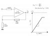
The easiest answer is to use a zener diode to make a suppressed-zero analog input. Eg, a 21V zener in a 24-volt nominal system, will make your analog input read (nominally) 0-10V for 21 to 31V input range. For 48V, I use a 2:1 divider and two 20V zeners in series to read 40-60V.
Adding a capacitor, around 1uF to the analog input helps reduce jitter.
I also read the A/D input and average it many readings.
")