In June, I decided to purchase an ECM-1240 from Brultech, but I had a lot of questions regarding what the pieces look like and how they really fit together. I also live in Arizona, so I was concerned about whether or not the heat in the garage would be an issue. Paul at Brultech encouraged me to avoid the hot garage and extend the unit. Here's a look at my installation, with the hope it will help others.
You can click on any of the pictures below to see a larger version.
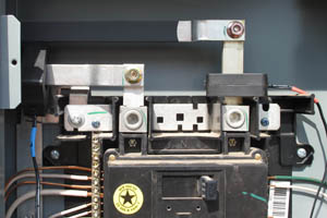
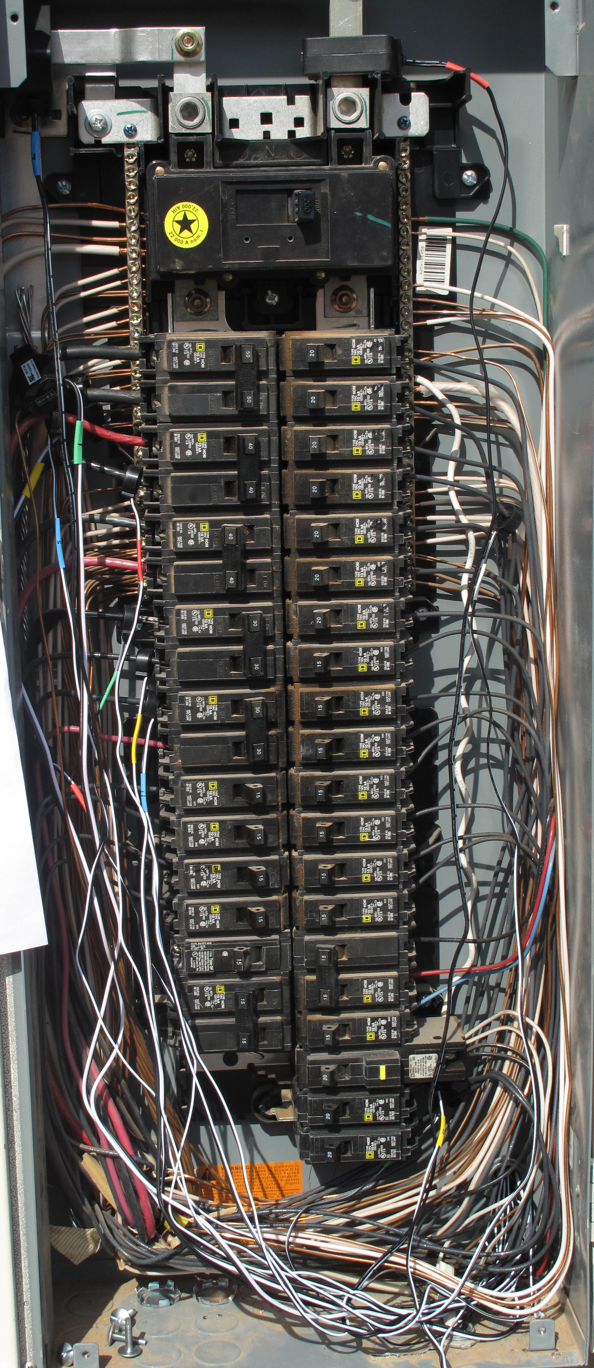
My first challenge was dealing with the main power feed over busbars. I expected a problem, so I asked about it, and indeed, they were too large to accept the normal CTs. Brultech substituted rectangular CTs on my order, as seen here:
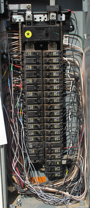
With that problem solved, the rest of the CTs were easy. To simplify installation, I put heat-shrink tubing on both ends of all of the CTs and then labelled each end with the circuit number. This allowed the electrician I hired for the panel work to quickly install everything where I wanted it. The entire panel turned out like this:
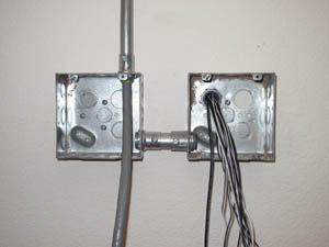
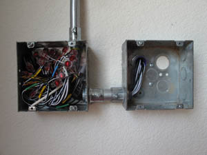
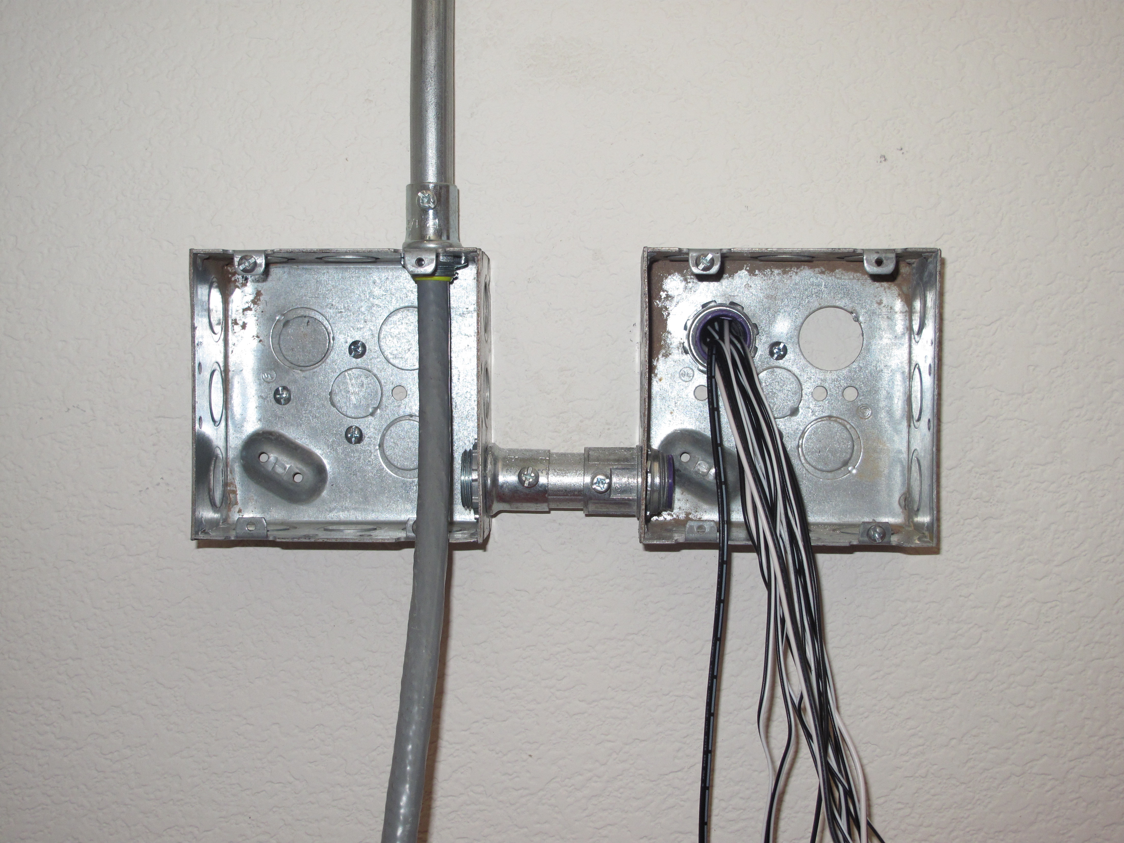
The electrician made a connection from the back of the panel straight into the garage and into a double-gang box. I had him install two double-gang boxes side-by-side. This allowed the entry box to remain suitable for other high-voltage work by moving the CT connections to a separate box. He linked the two boxes together and ran conduit up the wall from the second box. I had him run a 60 foot 25-pair cat 5E from the second box and into the house where the ECM was to be installed. At this point, things looked like:
Most of the circuits I plan to monitor on aux channels are two-phase. Brultech supports connecting two micro CTs to the same aux port by connecting the CTs together in parallel, but the documentation didn't state explicitly whether the CTs could be combined together and then ride over a single pair, or if they had to ride on separate pairs and then be combined at the ECM. Paul clarified that they should be combined at the ECM, so every CT ends up with its own twisted pair. Since I plan to add a second ECM in the future to monitor a few more circuits, I needed enough pairs that using a 25-pair cable became easier than running multiple 4-pair cables.
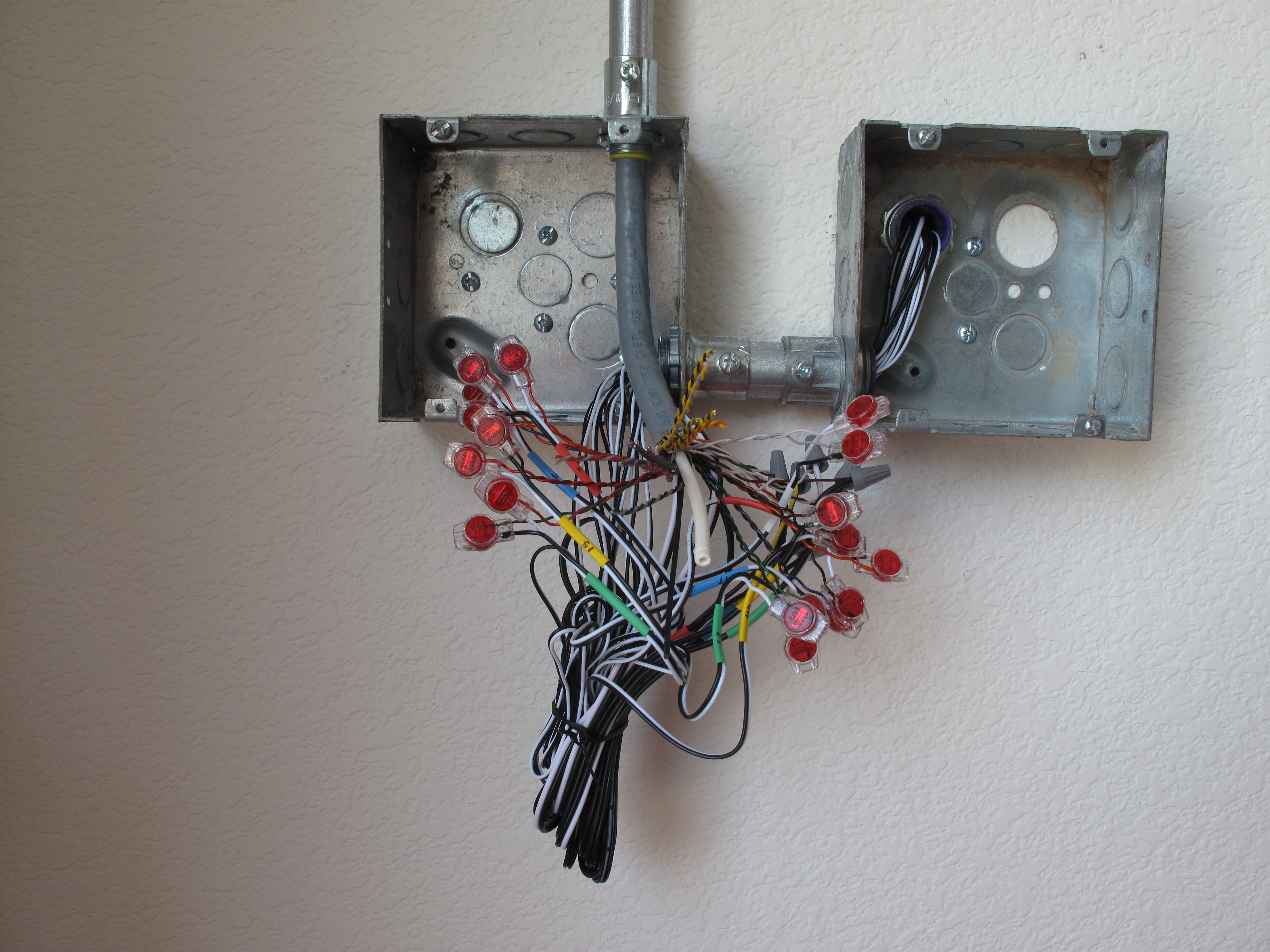
At this point, I took over the install and made the connections from the CTs to the 5E cable. For the micro CTs, I was able to use telco splice connectors, and for the larger CTs, I used small wire nuts. At that point, thing looked like:

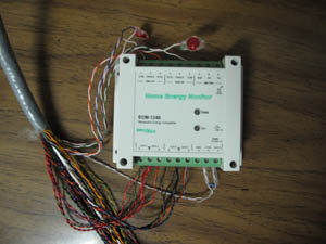
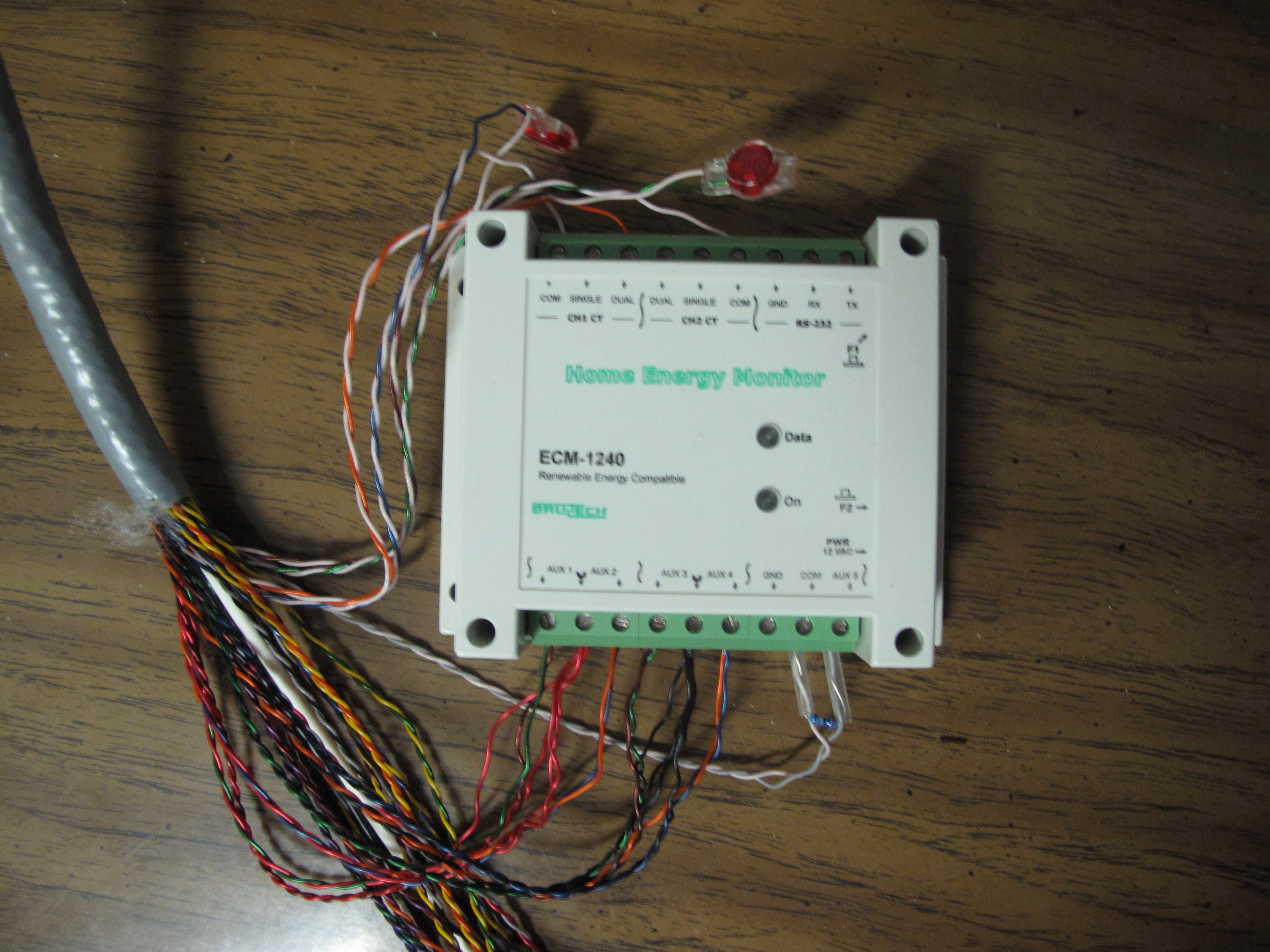
At this point, I went to the other end of the cable and tested each CT individually and then tested the ones that would be paired. This let me confirm that each connection was good and that polarity was correct. Once everything worked, the final result looked like this:
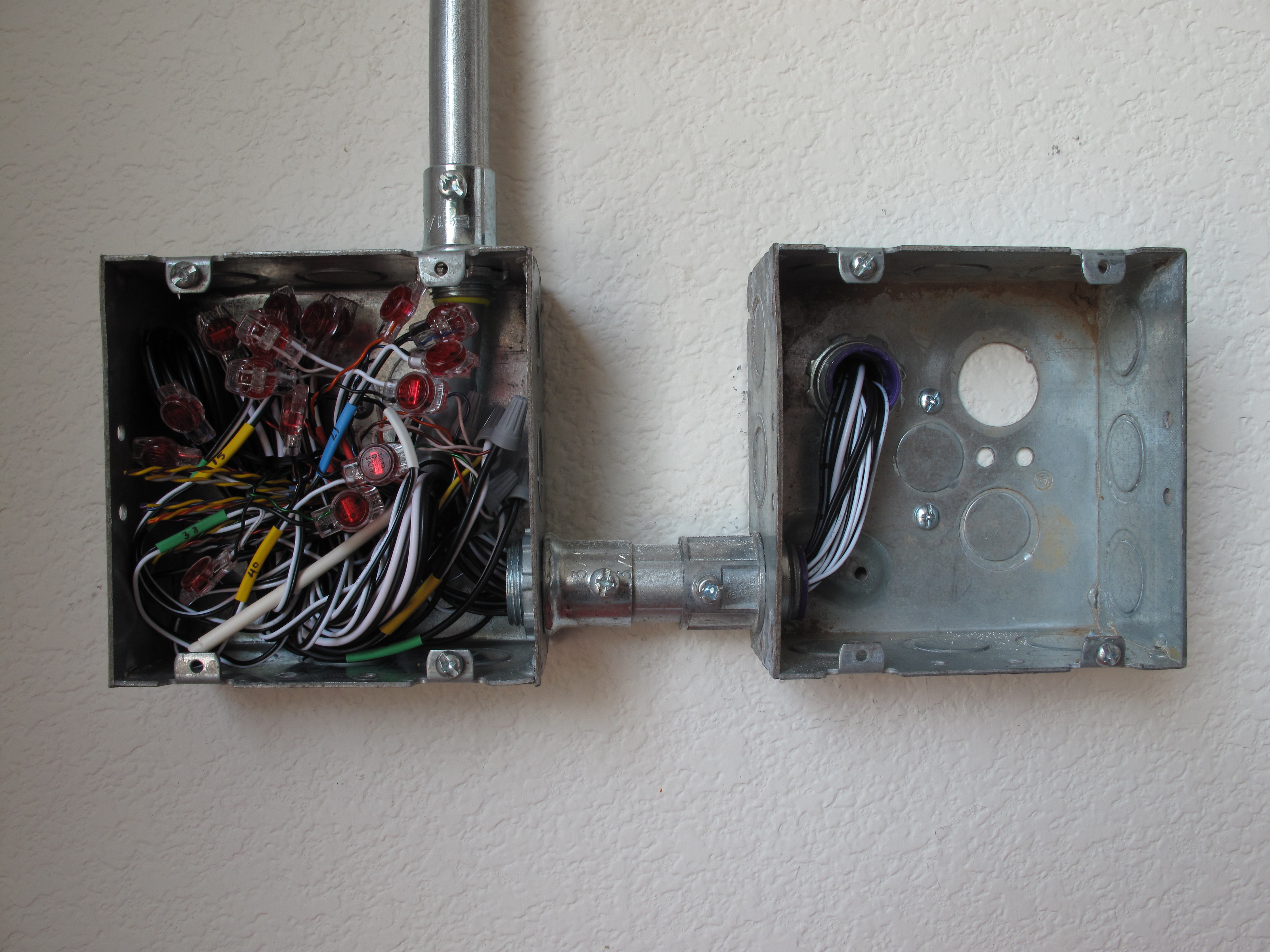
With everything reporting successfully, it was back to the garage to hide the evidence, which looked like this before the covers went on:
It would have been nice to be able to skip extending the CTs, but this solution worked out fine.
Now it's on to not only recording consumption but also using this information for automation purposes (e.g., when the washer or dryer stop drawing current, let us know so we can move the laundry forward).
Chris
You can click on any of the pictures below to see a larger version.
My first challenge was dealing with the main power feed over busbars. I expected a problem, so I asked about it, and indeed, they were too large to accept the normal CTs. Brultech substituted rectangular CTs on my order, as seen here:

With that problem solved, the rest of the CTs were easy. To simplify installation, I put heat-shrink tubing on both ends of all of the CTs and then labelled each end with the circuit number. This allowed the electrician I hired for the panel work to quickly install everything where I wanted it. The entire panel turned out like this:
The electrician made a connection from the back of the panel straight into the garage and into a double-gang box. I had him install two double-gang boxes side-by-side. This allowed the entry box to remain suitable for other high-voltage work by moving the CT connections to a separate box. He linked the two boxes together and ran conduit up the wall from the second box. I had him run a 60 foot 25-pair cat 5E from the second box and into the house where the ECM was to be installed. At this point, things looked like:
Most of the circuits I plan to monitor on aux channels are two-phase. Brultech supports connecting two micro CTs to the same aux port by connecting the CTs together in parallel, but the documentation didn't state explicitly whether the CTs could be combined together and then ride over a single pair, or if they had to ride on separate pairs and then be combined at the ECM. Paul clarified that they should be combined at the ECM, so every CT ends up with its own twisted pair. Since I plan to add a second ECM in the future to monitor a few more circuits, I needed enough pairs that using a 25-pair cable became easier than running multiple 4-pair cables.
At this point, I took over the install and made the connections from the CTs to the 5E cable. For the micro CTs, I was able to use telco splice connectors, and for the larger CTs, I used small wire nuts. At that point, thing looked like:
At this point, I went to the other end of the cable and tested each CT individually and then tested the ones that would be paired. This let me confirm that each connection was good and that polarity was correct. Once everything worked, the final result looked like this:
With everything reporting successfully, it was back to the garage to hide the evidence, which looked like this before the covers went on:
It would have been nice to be able to skip extending the CTs, but this solution worked out fine.
Now it's on to not only recording consumption but also using this information for automation purposes (e.g., when the washer or dryer stop drawing current, let us know so we can move the laundry forward).
Chris