Electricity Monitoring

jim3342

Member
I'm trying to install 2 split core current transformers to monitor electricity usage. I live in Canada and have 2 seperate 110V lines coming into my breaker box. The problem is that all the lines are black and I'm not sure which one to use or to even test which line to use.

I've put together a quick diagram and attached it. Can someone point me in the right direction, I've labelled the 4 lines A,B,C,D.
 

Attachments

Disclaimer: I am not an electrician.

The Service Entry Connection is normally a three-wire cable consisting of two black "Hot" wires and one white "Neutral" one. There'll be 240V across the black "Hot" wires and 120V between either Hot wire and Neutral. The white Neutral wire is grounded at the breaker box. If you measure voltage at any outlet, you'll see 120V between Hot and Neutral or between Hot and ground. There will be 0V between Neutral and ground.

Your drawing shows four wires and two of them are grounded. Based on what I described, the grounded ones may be the neutral wires. Why two Neutral wires? No idea.

I highly recommend you consult with a qualified electrician before installing the "split-core transformers". Better safe than sorry.
If they are not approved devices (i.e. CSA, UL, whatever) and they cause damage to your home (use your imagination) ... your home insurance company will not be your friend.
 
i am preety sure multi meters will display +/- values depennding on which leg is hooked to common vs ground /neutral in a 120 A/C volt circuit (just as they would in DC). If so check voltage between A/B and C/D to figure which is hot.

on two of your legs, voltage between say A/C should be 240 (if on different phases form the transformer) and B/D should be 0 (o interchange C/D in the associations)

for what my non-expert opinion is worth, "qualified electrician" is a waste of money ;) you're better off buying a multimeter and a good book :) I have yet to find an electrician locally who can understand what i've wanted or done in regards to HA. I sent all my NEC questins to an expert forum - no one would touch it with a ten foot pole...

-brad


So if A & C measure 240 then they would both be the hot wires and I should put the CT's on those lines?
 
ok i stand corrected (certainly wouldn't be the first time)...

Still take the other legs and unless the two hots are same phase you could still infer it form the results without paying anyone money...
 
So if A & C measure 240 then they would both be the hot wires and I should put the CT's on those lines?


On the first part, yes but that would only be true if they are not the same phase (otherwise it would be like touching your leads to the same common wire on a socket)... regarding the transformers, that's one i don't know and won't comment on given my blunder on the meter readout!
 
That's weird. Can you post an actual photo? Where is your electric meter in realation to all this?

I can think of a couple of things .. parallel main feeders ... or your diagram is wrong.
 
Here is a picture of my breaker box.

I'm not sure if this helps but I just did some multimeter tests.
a & b = 240 V
a & c = 0
a & d = 240
b & d = 0
b & c = 240
c & d = 240

Any help with this is appreciated.
 

Attachments

  • breakerbox2.jpg
    breakerbox2.jpg
    172.6 KB · Views: 69
Jim,

Take a picture from about 8 feet back so we can see what is feeding into and out of your breaker box please ?

Is this service in a house or apartment ?

Thanks
Neil
 
If I go any farther back it's only drywall. The panel is in the basement and the walls are finished.

It's in a house. I just a look outside and it looks like the top feed is coming from my outside meter
 
for what my non-expert opinion is worth, "qualified electrician" is a waste of money ;) you're better off buying a multimeter and a good book :) I have yet to find an electrician locally who can understand what i've wanted or done in regards to HA. I sent all my NEC questins to an expert forum - no one would touch it with a ten foot pole...
-brad

Yes, my thoughts precisely! :P 
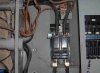
Not to start any friction here, but I know there isn't any standard electrician in my phone book that has the foggiest idea about integration of electrical and home automation/security. Oh the money it would cost if you could find some people qualified to do it. It still wouldn't be they way I want it anyway.

On the other hand, I do respect electricians when it comes to standard stuff. I use them all the time at work. Leave the control integration to me though.

As far as this post; you should get your hands on one of these - veris 8035 or 8036 - you need a modbus master though. The device does all the calculations for kW/kWH and even more with the 8036. I know there's a 8035 on ebay right now for 159.00. Just search for "veris 8035".
 
To me, it looks like the bottom conduit, 3 cables, is your main feed, hot-hot-neutral. Its connected to the "main breaker", which is protecting that panel. From this picture, I don't see how else the breakers in that panel could get fed. Then its feeding through that breaker to somewhere else via the top conduit. Does that top conduit go to another subpanel or what? I know you said you think it comes from the meter, but I don't think the POCO would install a bare neutral in metal conduit.

By your diagram the that 3rd insulated cable that comes out of the lower conduit is connected to the panel ground, but it almost looks like it heads right back into the upper conduit.

You should post that on an electrical forum and see if somebody can tell you what's really going on or if its even legal and/or safe.
Try http://ths.gardenweb.com/forums/wiring/ There's some Canadian electricans that hang out there, ey?

Anyway, your original question was where to hook up the CTs. You've established that you have 240 on both A&B and C&D.
I'd put the CTs on the lower C&D cables so they won't interfere with operation of the breaker.
 
Jim:

I'm not familiar with an input that looks like yours. Did you perform those measurements with the breaker in the "off" position? Something isn't making sense in my head (mainly what is feeding lines C & D).
 
Considering it's December in Canada I don't think I'll try these tests with the power off tonight with the family home. It's a good idea and I'll try it during the day tomorrow.
 
Back
Top