I need some pointers please. I am trying to set up alerts in the garage to allow me to hear if a sensor is triggered in the main building.
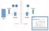
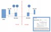
Here is my setup:
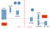
Do I hook this up to the M1DBH (if so how? It does not seem to go on the bus) or do I need an extra run from the M1G from the OUT 1 (or 2, 3)?
If it goes to one of the OUT - how does it know what recording to play?
Here is my setup:
- House: M1G, M1XIN, M1DBH, multiple KP in the main building
- Garage: M1DBH, M1XIN, KP in the Garage.
Do I hook this up to the M1DBH (if so how? It does not seem to go on the bus) or do I need an extra run from the M1G from the OUT 1 (or 2, 3)?
If it goes to one of the OUT - how does it know what recording to play?