How do I conncet pot to M1

znelbok

Active Member
Hi guys

I want to add a 10 turn pot to the M1 to record the position of a rotational device (lets say garage door for the example as we are all familiar with garage doors)

So I attach the pot to the door shaft that turns as the door goes up and down.

From that I want to get the exact position of the door at any point along its travel.

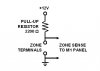
What I cant work out is how to connect the pot to the M1.

I have in past remove the pull up resistors on some inputs so the M1 can measure voltage only (i.e. no 12V from M1 on the input) and use this successfully with the 4-20mA 24VDC transmitters that I have.

Mick
 
Thanks for the fast replies

I tried it across a zone (had a 1K and 10K pot handy) and got no real response that was usable.

I will try to find a 2.2K pot and give that a go I suppose.

I did know about the other thread, that's why used the garage door as an example so people could better visualize what I was trying to do.

Mick
 
Reference this schematic from that garage door how-to Steve linked to:

gdc.jpg


The pot should have three terminals as shown. Terminal 1 will to to the Elk's plus 12 volt AUX source, Terminal 2 will go to the positive input of a zone set as analog, and Terminal 3 will go to the ground input of that same zone. I believe that the zone's grounds are the same reference as the AUX 12 volt source ground.

Go to the main panel in RP and look at the zones voltage values. Turn the pot and see if the voltage changes. If you want to change the direction of rotation related to voltage, switch terminals one and three.

If the pot value is low enough, you may not even need to over-ride the pull up resistors.

If you are using an zone expansion card, I believe the refresh rate is around 30 seconds or so.
 
Thanks

Here is my issue with this circuit

You have 12V from the Aux on pin 1 and you have 12V from the Zone on pin 2 - that is why I did not think that this would work.

I admit that I dont fully understand how the pull up resistor woks in the circuit.

Maybe I should have tried the Aux on Pin 1, the zone input on 2 on a zone with the pull up removed and common zero's.

Mick
 
Depending on the pot's value, the pull up resistor could have little effect, or make the circuit non-linear, or not work at all.
The internal 2.2k pull-up would have little effect on a 100 ohm pot, but would really mess with the linearity of a 10k ohm pot.
 
I admit that I dont fully understand how the pull up resistor woks in the circuit.


Look at Lagerhead's post above.

The pull up resistor simply keeps the input signal from "floating" or varying randomly. It keeps the input pin at 12v when open. When there is a zone resistor in place, a resistor divider network is created that would put the input voltage at 6 volts. When the zone is shorted the zone would be at 0 volts.

My numbers may not be exact put it gets the point across, hopefully...
 
If you want linear response then the value of your potentiometer should be 2200 ohms.
This was soooo wrong. You can't get linear response in this application with a linear taper. Here is why (assumes 12 V where it is actually something over 13 V):
 

Attachments

  • zoneplot.jpg
    zoneplot.jpg
    39.3 KB · Views: 22
I got hold of a 2K pot yesterday and the results are not good so far.

Apart from having a pot that was faulty (open circuit across outside pins and O/C from middle to one outside pin), I had a variable resistance between pins 1 and 2. Unfortunately, the M1 just would not update with the voltage at all in reasonable time.

The max voltage I could get was 7.1V (voltage divider circuit with pull up resistor - so that's OK), but as soon as I wound it down it could take up to a minute for the value to change with in the M1. The DVM showed the volts changing as I would expect, but it was not fast enough for use as anything for control. I have other analog inputs on the same card that were updating much much faster so I an not sure what is going on. I have a replacement pot on the way so I can do some more testing when it comes in.

Mick
 
The pot value is going to need to be lower, a lot lower. At 150 ohm, you're going to suck a lot of current through it (80 - 100ma), but It will work.
Not a perfect linear, but close.
 
Apart from having a pot that was faulty (open circuit across outside pins and O/C from middle to one outside pin), I had a variable resistance between pins 1 and 2. Unfortunately, the M1 just would not update with the voltage at all in reasonable time.
Re-read my above post, if you have an expansion card and are using an analog type zone, the M1 will not scan that card's zones for some time. Check out THIS post for more information.
 
Back
Top