Humidity Sensor connection mystery

Tschmidt

Active Member
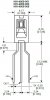
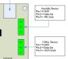
Hopefully someone at CAI Networks can help with this mystery.   I've used WebControl 8's for several projects, including the HIH-4000 humidity sensor. My current project is an outdoor temperature/humidity data logger. But when I tested this one and mounted the HIH-4000 directly to the WebControl8 terminal strip, per the picture, it blew it up.   https://sensing.honeywell.com/honeywell-sensing-hih4000-series-product-sheet-009017-5-en.pdf   Looking at the HIH-4000 data sheet Vcc/ground are opposite of how the WebControl8 manual says to connect it. What baffles me is I've used several of these humidity sensors in the past connected per the user manual and they work fine. I looked at old WebControl and HIH-4000 data sheets and they have always used the same pinnouts of both the board and the part.   This is a $15 dollar part so I'm hesitant buying another one and connecting it in reverse to see what happens. If the documentation is incorrect - why have the senors worked in the past?  
 

Attachments

  • SensorTerminalBlock.JPG
    SensorTerminalBlock.JPG
    50.8 KB · Views: 12
  • HIH4000.JPG
    HIH4000.JPG
    35.7 KB · Views: 10
  • BoardLayout.JPG
    BoardLayout.JPG
    20.6 KB · Views: 10
I also used this sensor but I never relied on the documentation; I just used multimeter to check where +5V and where ground and connected accordingly based on the sensor's datasheet.
So if you connect it based on where real 5V and ground is and if +5V is stable (no issues with internal 5V switching power supply on the board), the sensor should not blow up...
 
If the sensor is connected correctly, it should not blow up the sensor, unless the board is defective or the sensor is bad. The number 2 terminal is for reading the voltage on the sensor output pin only, it should be like a floating near zero without anything connected.  Please make sure pin 1 and pin 3 are not reversed.  Since the board is mass manufactured, it is impossible to have any board reversed pin 1 and pin3 on the PCB, unless all the boards are bad.  However, we tested every batch of boards for every function before production, so that power on board could not be reversed.
 
I confirm that pin1 is GND and pin3 is 5V. The Honeywell sensors we have both sides have windows. Please note the orientation of the sensor, the side up has a tiny line of letters printed near top of the sensor.  The other side sensor has window, like Tshmidt shown, has no letter printed on top of the window.
 
CAI, thanks for the additional research. The one I recently purchase has a window on one side and a glued on white tag on the back with a calibration #. I peeled off the tag and that side looks just like the picture in the user guide, appears to be the chip leadframe. Well at least that solves the mystery of why the others worked before I blew up this one.  I don't remember every having one with the calibration tag. Thankfully is was not a hugely expensive chip. 
 
The next time you guys update the user guide be a good idea to expand proper Humidity sensor insertion. 
 
Thanks for clarification!  One should remove any tag paper covering the sensor window, since humidity is detected through those window.  Don't know from when they started putting those tag on the sensor, I would think they should have a note to ask users to remove any glue paper on the sensor before using.
 
Tschmidt, as you suggested, we added another warning message next to the sensor wiring picture in the user manual. Hopefully your loss would prevent others from that kind of losses in the future.
 
CAI_Support said:
  Don't know from when they started putting those tag on the sensor, 
The label is on the "back" side of the sensor. It has a printed number that matches the calibration report.  
 
Back
Top