CAI_Support
Senior Member
I would remove TSTEQ from the picture, just say what ip1[1000] return. That is simpler to comprehend for me.
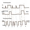
For low to high going pulse, if say the pulse is low one hour, 5V for 500ms, IP1[1000] will return FLASE.
Same pulse, for high to low logic, the logic expect IP1[1000] to return TRUE all the time.
The expectations are directly conflict.
For low to high going pulse, if say the pulse is low one hour, 5V for 500ms, IP1[1000] will return FLASE.
Same pulse, for high to low logic, the logic expect IP1[1000] to return TRUE all the time.
The expectations are directly conflict.
")