Temp sensor connections

edlentz

Member
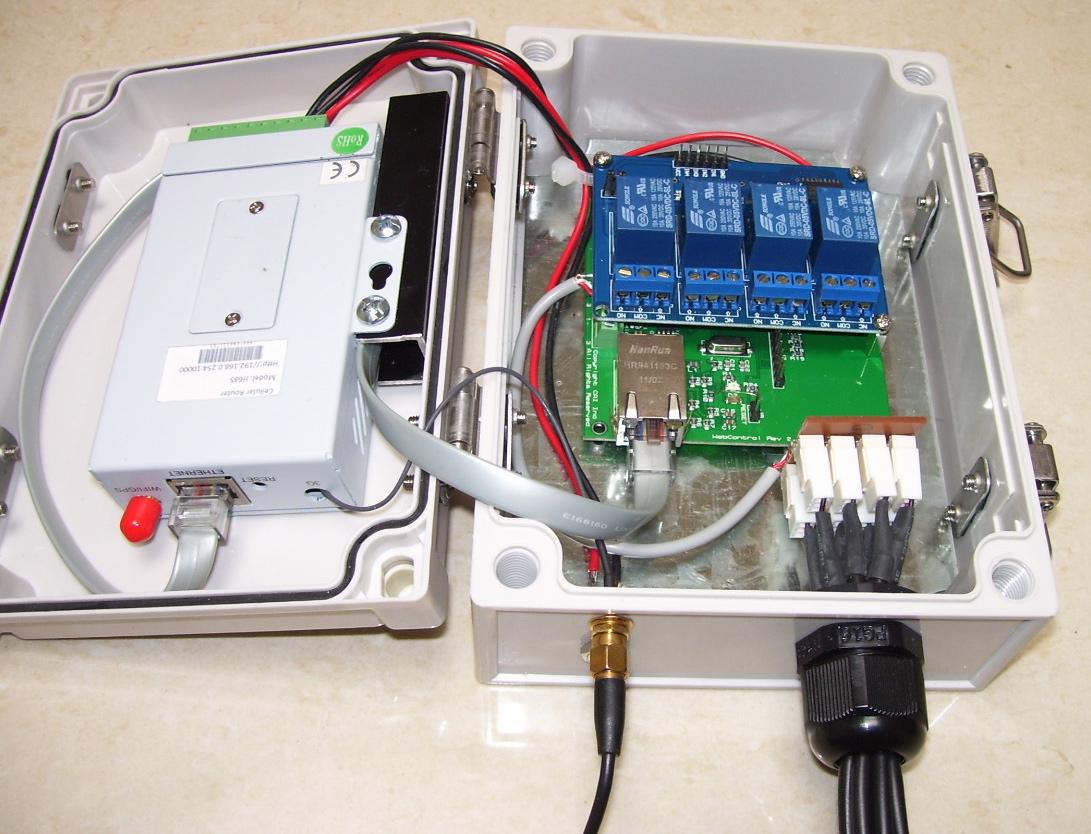
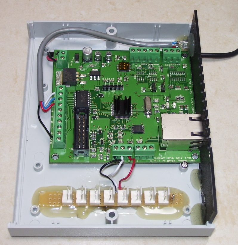
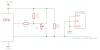
Ok so I have 6 sensors connected and I had a pretty hard time getting them all connected to the board. I want to connect a couple more. What do you guys use? I am thinking about some terminal strips to break it down to a couple per terminal. Maybe I will create a board to connect them to. Haven't decided. At the moment I have used separate cat5 for each two sensors. One sensor on the Blu - Org pair and one on the Grn - Brn pair. I found that I could not get multiple sensors to work on the same wires ie: two sensors on the Blu - Org pair. My wiring is :

#1 Wht/Blu
#2 Blu/Wht
#3 W/Org
Org/Wht -- Spared not used.

I thought that this wiring would pair the Data wire with the Gnd wire to shield it somewhat.

Anyway if anyone has any suggestions they would be much appreciated.

Thanks
 
Anyway if anyone has any suggestions they would be much appreciated.

I buy sensors pre-made with a 3-pin plug, and then made a "strip" to connect them to the WC board, thus:
100_4857.JPG


In a different application, I made a prototype "string" that is used for measuring stratification layers, and feeding around inside computer racks.
100_5058.JPG


100_5062.JPG


The connector idea can be done in different arrangements to suit the application, eg:
100_5170.JPG


and
100_5048.JPG
 
Update to my sensor setup: In checking the status of my system 4 of the sensors in fail mode. The only thing that changed in the house was I shifted my butt in the chair. The furthest length of cable for any of the sensors is about 25 feet. that is the one for the outdoor sensor the others are within about 15'

Thanks
 
I found that I could not get multiple sensors to work on the same wires ie: two sensors on the Blu - Org pair.

What hardware revision board? I had huge problems with the early boards running multiple sensors - they were only being supplied with 3.3V. In the end, I overcame my problems with these old boards with a combination of: (a) running a wire link on the board to get +5V to the sensors supply, and (B) adding a 4K7 pullup resistor to the data line. Ideally at the end of the longest sensor, but I just put it on my jumper board and it has worked "well enough".
 
Update to my sensor setup: In checking the status of my system 4 of the sensors in fail mode. The only thing that changed in the house was I shifted my butt in the chair. The furthest length of cable for any of the sensors is about 25 feet. that is the one for the outdoor sensor the others are within about 15'

I use 3m cables on my sensors (thats near enough 10') - but 8 of them running in parallel. Not Maxim's ideal configuration, but works.
I have one system running with 7 x 10' and one that is 100'. I added a 4K7 pullup to the far end of the 100' run. It works fine.

You might try power-cycling the whole kit. Once the sensors get locked up, it seems to need a powercycle to recover. I've found short resets are often not enough, turn it off for over 10 seconds, then back on.
 
Do you have temp sensor timing adjustment on your firmware general tab? Older firmware does not have that. Newer firmware has that adjustable.
 
I buy sensors pre-made with a 3-pin plug, and then made a "strip" to connect them to the WC board, thus:

rossow-- where do you get your sensors, and parts. My temp sensors are up against copper piping and I am not sure they will last the way I have them against the pipe. I like the individual connections. That way if I have a bum sensor I can replace it quickly.

fwd03 -- I do have the adjustment on the web gui. I tried to adjust it but that didn't have much affect. After a power reset I have 7 sensors up and running and appear to be stable.
 
rossow-- where do you get your sensors, and parts. My temp sensors are up against copper piping and I am not sure they will last the way I have them against the pipe. I like the individual connections. That way if I have a bum sensor I can replace it quickly.

I have them made for me a few hundred at a time.
I also have heaps of them attached to copper pipes and Brass fittings. There are some tricks that are not immediately obvious that I should mention - but I'm traveling interstate today and tomorrow, so it'll have to wait until I get back.
 
I've found that a fault with any temp sensor requires a power cycle. Once the fault is set cycling the power seems to be the only way for the board to rediscover the temp sensor I.D. I have about 50 feet of catV with several Y's run from my living room to my wood/oil furnace and outside. The temps are very stable and I have no issues unless I unplug one of the sensors. I crimped the temp sensor into an RJ45 connector. They fit perfect. Just need to be careful crimping so you don't crush into the case. I also use the stainless steel encased ones. Wish I had seen Ross's plugs before I did mine. I'll use them on the freezer project.
100_1548.JPG100_1549.JPG
 
If all temp sensors having same length of cable, you will have problem, because electrical wave from 7 end points bounced back to the board together. It is better to have different length cables. The best way to wire them is running one cable trom board to first sensor, then next, then next. CAT5 header will have problem to crimp them, if you want two wires going into one position. What I did was to have CAT5 cable stripped near the sensor location, then solder a 3 pin header on the CAT5 cable. Then I solder the temp sensor to a short stab cable, then solder the other end of the cable to the little socket that plug on top the 3 pin header. I think Dallas Semiconductor having a document talked about the stab wire length.
 
I am a tinkerer at heart and tend to rush off and hook stuff up. I'll DL the Maxim Doc.

rossow I will take any tips and tricks you want to share anytime.

Thanks
 
Today I connected a second temperature Those switches like this http://www.ebay.com/itm/281098385021. Those switches are connected in parallel with a conventional chip DS18B20 enshrined in the contacts on the board. Those switches are both uncertain, but indicate the temperature by 2 degrees different, although both elements are close to each other. Why can such a difference?
Also, I also want to ask how do you properly connect multiple Those switches at great length.
So far I have found such a scheme. See attached.
As far as it is efficient for the WebControl?
I would appreciate any comment
 

Attachments

  • 2-podkluchenie-ds18b20-ds18s20.png
    2-podkluchenie-ds18b20-ds18s20.png
    3.3 KB · Views: 11
Back
Top