DC power UPS?

I did a rough-and-ready test on the two candidate power banks.  Initially they both draw power just from their batteries and none from their input.  On the Lime, in about an hour it starts the recharge process, and it appears to be just above the amount of power being drawn.  On the other power bank it takes about 3 hours for the charging to start.  Initially it charges at a much faster rate than power is being drawn from it, but it gradually tapers off and then, like the Lime, it appears to draw just a bit more than what's being drawn from it.
 
So, although it's not great news that they initially draw power from the battery, it appears that the charge cycle is never terminated because of the outgoing current.  The batteries on both remain cool, and the charging circuitry is only modestly warm.  I'll have to run some much longer tests to confirm that the charge cycle *never* terminates, but if it never does, then at least they won't be charge-cycling over-and-over, which would have led to premature battery failure.  As it stands, it looks like they may function as a kind of "float charger" UPS.  I don't know what the effects of that may be on a lithium ion battery though.  As long as the batteries aren't overheating, is there any reason for concern? If so, then it's game over.
 
Just about everything I'm reading says not to float charge a lithium-ion battery.  So,I'm done with it.  What battery chemistry other than Lead Acid can be safely float charged?  It appears that float charging is perhaps the simplest circuit for a DC UPS.
 
Are you sure that the battery is allowed to continue charging and the charging circuit never shuts down?  I'm not sure I understand how/where you are making the measurements.  If you are measuring the current going into the unit from the wall vs the current being drawn out, I don't think you can conclude that the battery never stops charging. 
 
It seems like any halfway decent Li ion charger needs to cut off the charging, otherwise you could never just leave it plugged into the wall past the point that it reaches full capacity just for recharging purposes.
 
RAL said:
Are you sure that the battery is allowed to continue charging and the charging circuit never shuts down?  I'm not sure I understand how/where you are making the measurements.  If you are measuring the current going into the unit from the wall vs the current being drawn out, I don't think you can conclude that the battery never stops charging. 
 
It seems like any halfway decent Li ion charger needs to cut off the charging, otherwise you could never just leave it plugged into the wall past the point that it reaches full capacity just for recharging purposes.
You are correct.  Maybe it does shut-down the battery charging.  I can't be sure though because there's no obvious way to access what's inside the power bank without risking a potentially destructive tear-down.  Is there another way to check without that which will yield certainty?  
 
Yes, I was just looking at voltage and current going in versus voltage and current going out.  The outgoing is essentially constant, so it reduces to just looking at the ingoing.
 
I'm aware that some lithium ion charger circuits have a timeout feature as a kind of failsafe to avoid constantly charging the battery, but I don't know whether either of the two power banks have that.  I don't want to worry that one or the other might burst into flames somewhere down the road, especially when leaving it unattended.
 
Mea
 
The Lime didn't come with a user manual.  However, the EasyAcc Powerbank Bolt 1600S did.  Buried within the user manual  (page 4) it says:
 
"Note:  A full charge will take about 4 hours using the included charger.  Please remove the charger when Bolt 1600S has been fully charged.  Overcharging may cause damage to Bolt 1600S."
 
On page 6, it says: "Do Not leave the charger plugged in at all times."
 
On it's face, that disqualifies the EasyAcc.  Maybe it's the exception, but it gives me an uneasy feeling about the Lime without some way to verify.
 
NeverDie said:
On page 6, it says: "Do Not leave the charger plugged in at all times."
 
On it's face, that disqualifies the EasyAcc.  Maybe it's the exception, but it gives me an uneasy feeling about the Lime without some way to verify.
 

Well, that sure is discouraging.  I wonder how much margin of error there is between the time the battery is fully charged and before damage occurs.  At least the instructions make it clear not to leave it plugged in. 
 
I'm surprised they didn't design it so that it stops charging once the battery is charged. I'm sure that many users will forget and end up being pissed off when it kills the battery and never buy their products again.  Including a cutoff comes down to making happy customers.
 
@RAL:  You may find this interesting:  http://www.righto.com/2012/10/a-dozen-usb-chargers-in-lab-apple-is.html  It includes an Apple iPhone and and Apple IPad charger in the comparisons.
 
I found out the reason why a 5V 2amp power source is recomended for the Raspberry Pi B+.  It's to ensure ample power for USB devices that might be drawing power from its 4 USB ports!    B)  
 
In any case, I've decided to provide power directly to pins 2 and 6 of the pi (see http://www.mosaic-industries.com/embedded-systems/microcontroller-projects/raspberry-pi/gpio-pin-electrical-specifications for pinout) and thereby avoid all the issues that come from providing power through the USB.  Presently I'm planning to use the Belkin as the 12v UPS, knock its power down to just ~5.4 volts (= 5.0v + whatever the dropout voltage incurred by the adafruit LDO regulator below) using this step-down converter, which arrived yesterday: http://www.ebay.com/itm/321243758553?_trksid=p2059210.m2749.l2649&ssPageName=STRK%3AMEBIDX%3AIT ,
 
$(KGrHqF,!lEFJn4fv)cDBSegq,R2Iw~~60_57.JPG

 
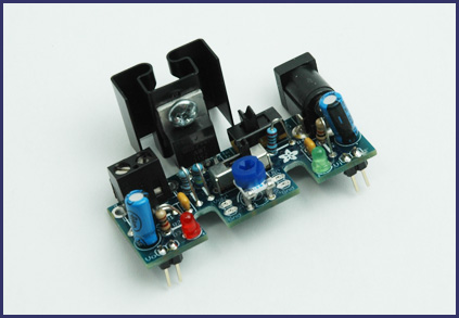
and then mount  this very low dropout voltage regulator on a HAT as the final stage to hopefully provide very clean 5v power directly to the pi's pins 2 and 6:  https://learn.adafruit.com/adjustable-breadboard-power-supply-kit/overview
 
aDSC_1035.jpg

 
I ordered the adafruit voltage regulator yesterday, only because the dropout voltage will be in the 40mv to 400mv range, so as to minimize the amount of heat.  Its maximum current is just 1.5 amps (not 2 amps), but I'll add a self-powered USB hub (or else self-powered USB devices) should that ever become an issue.  I would have preferred using a pre-assembled equivalent rather than a kit, but I had no luck finding anything pre-assembled with a similarly very low dropout voltage.
 
Applying power directly to the GPIO pins bypasses the polyfuses, but since the buck converter (above) let's me dial-in whatever current limit I want, I'm hoping it will be just as good.  I did test the buck converter last night at powering a 5volt 2amp dummy load, and it barely got warm.  I'm happy about that.  I'm not sure the adafruit voltage regulator is actually needed, but I presently have no oscilloscope for checking the buck converter's output for ripples or noise.  Supposedly the ripple is less than 50mv, at least according to the description in the ebay listing.  While I wait for adafruit regulator kit and the HAT prototyping board to arrive, I may try running the pi directly from the buck converter to see how well the pi fares with it, in which case the HAT mounted adafruit LDO regulator would be the fallback plan if the pi fares badly without it.  
 
Is there's a good converter that will go directly from 12 volts to 5 volts without producing much heat and which has low ripple and low noise?  If there is a magic bullet like that (e.g. maybe this? http://www.adafruit.com/product/1065), it would simplify matters and reduce costs.  I wasn't sure, so I'm presently taking the more conservative path outlined above.
 
Although this DC UPS evolved in a pi context, it's a straightforward (albeit brute force) solution, and I would expect the same general approach could be adapted to just about any microcontroller or DC device that would benefit from a DC UPS.  I'd still be interested if anyone sees a better way to do it, as I'll probably be replicating either this or a variation of this for other DC devices that I want to provide with a DC UPS.  For instance, I expect the Belkin 12 volt UPS could be substituted by a SLA battery connected to an Elk or Seco charger (supplemented with the Elk or Seco low battery cut-off, as described recently in a different cocoontech thread: http://cocoontech.com/forums/topic/27267-protecting-sla-battery-from-over-discharge/?hl=+low%20+battery%20+cut#8208off= ).  Then the only remaining issue is how best to cleanly package it all up neat and tidy to keep the dust off the heatsinks while still allowing adequate ventillation for the SLA battery.  I suppose the default would be an alarm panel enclosure, but if anyone knows of something better, please post.
 
@NeverDie -
 
Thanks for the link to the charger comparison.  I think I had seen that one a while back, but it was worth reading again to refresh the details.
 
I think you are doing the right thing by delivering power directly to the Pi's circuit board and bypassing the USB connector.  Hopefully, the buck converter will have sufficient regulation so that you don't need to use the Adafruit regulator.  Would be nice to keep it as simple as possible.
 
I hadn't come across the Traco TSR12450 before.  Looks nice and is something to keep in mind for some future project. 
 
Well, I finished my build and it has been running for two weeks.
 
Here is a link to my parts list post earlier in this thread:  Link
 
And this is a simple diagram of how I finished out the project:
DC-UPS.gif
 
How long do you reckon your lifepo4 battery will last?
 
When I unboxed  the APC that I had purchased on sale, I noticed that its SLA battery had been manufactured 18 months earlier.  Initially I was afraid it had discharged while sitting on the shelf for so long and that it would be ruined, but, interestingly,after I powered it up it still had a voltage of something like 12.9 volts while driving a load.  Is that normal for an SLA, or did they tweak the battery to give it longer shelf life?
 
I thought NeverDie's question was worth investigating.   The life time of the LiFePo4 batteries vs their added cost is an important question when/if the use case is a UPS, not a mobile use case like a golf cart where the weight is a factor in the evaluation.
 
The analysis by this user was especially useful.  
http://ka7oei.blogspot.com/2013/05/lithium-iron-phosphate-lifepo4.html
 
It was a good read, I recommend it to every one with an interest in this topic.
 
I wanted to report that my UPS based on a LiFePo battery hasn't missed a beat since it was installed.
 
This battery chemistry looks like a good balance of lifespan, charge/depletion cycles, and cost.
 
In contrast, the sealed lead/acid battery in the security sub-system had to be replaced in the intervening years.
 
I'm looking at one of the OpenUPS2 units for a 12vdc PC to be put in a boat.  If only to provide a data signal to do clean shut downs when the breaker gets turned off.  
 
Here utilize an intelligent PS on the CarPC's using similiarly pictured case.  The case/PC are DIN mounted and easy to remove for storage.  They also sell connectors for the case to be DIN rail mounted. Built a small footprint HS3 server for a peer using one of these cases a few years back. Running fine today.

Make it a winter project baby steps fashion using a new Skylake mITX board. (very fast and low powered).
 
Here use one storage drive and one SSD for OS boot on Windows embedded.  Thinking of switching over to using Ubuntu / KODI.  As previously mention the computer video connects to a device which appears on the automotive bus and is seen in the HU display as a component.  (radio, satellite, GPS Navigation, telephone are components seen on the HU).
 
Two power leads to the PC.  One connected to ignition 12VDC power and one connected to the 12VDC automotive 12VDC battery.  You can program the power supply and typically here the PC shuts down in seconds.
 
Adding a UPS with batteries would be nice and similiar to years ago use of a tank battery.  Tank battery was always being charged and the PC would run through a circuit and the battery.
 
UPS.jpg
 
Back
Top