DC power UPS?

Automate said:
Agreed, I don't think this should be a big issue.  Even the most simple power supply is going to have some amount of inductive or capacitive filtering.
 
Remember we are talking about AC so at 60Hz the input voltage is going to zero every 8.33ms anyway.
 
10ms is just over half of a single sine wave.  Not much in the big scheme of things
 
While it is true that the AC voltage goes to zero every 8.3ms, that's not what is important.  What is important is the amount of energy being transferred when the voltage is not zero.
 
The UPS spec allows for a drop out of up to 10ms, which is a bit over 60% of one complete AC cycle.  So the power supply would have to have that much stored energy to fill in the gap.  That may not seem like much, but it actually is.
 
A typical Raspberry Pi draws about 1.0A at 5V, or 5 Watts of power.  During a 10ms drop out, that would be 0.05 Joules of energy.
 
A quick, back of the envelope calculation says you would need a 4000 uF capacitor to store that much energy.  
 
That's a pretty big capacitor in terms of physical size, and would take up a large fraction of the space available in a small, wall wart type of USB charger.  I doubt that any of them have anything close to enough capacitance to sustain the output during a 10ms power drop.
 
As pointed out, a typical capacitor filter for a 60Hz PS has to carry the full energy drawn from one peak of a full wave (or half wave) to almost the next waveform peak or slightly less than 8.3 ms. These Universal PS units are good for 50 Hz also. Now we are talking the full 10ms anyway.
 
Since 10ms is no longer than the normal PS cap responsibilities something has to be wrong with that analysis. I suspect the discharge parameters are not correct. In particular has the energy carry-over of 120 x 1.414 peak charge = 170 vdc down to say 50-60vdc cut-off operating range of the chopping inverter been accounted for?
 
Too lazy to do it right now but I would like to see the calcs for a 4000 uf x 400vdc cap. Something doesn't sit quite correct there yet.
 
I did my calculation based on the 5V output of the charger, hence the large value cap required.  But you're right, additional capacitance using a smaller value, higher voltage cap on the input side, after the rectifier, is another solution.  I should have considered that.
 
USB chargers using a switching design usually have caps on the input side anyway. The trouble is, most of the inexpensive USB chargers use a really cheap, lousy design.  Some of them use only a half wave rectifier and a 4.7 uF capacitor on the input side.  Barely enough to continue to provide power during the missing half cycle.   But even on the somewhat better chargers that use a full wave rectifier, the tear downs I have seen still use a 4.7 uF capacitor.  By my calculations, that's still not enough to make it through a 10 ms power drop out.  I believe you'd need at least a 7.5 uF capacitor when running with a 120V input.
 
The only charger design that I have come across that looks like it might be adequate is the Apple iPad charger, which has a 6.8 uF plus a 10 uF capacitor on the input side.  The iPhone charger is close, but not quite good enough.  It has only a 6.8 uF capacitor.
 
In Apple's case, although their chargers are rather overpriced, they really are a better design.  Samsung makes a pretty good charger, too, but not quite as good as Apple's.
 
You really do need to look though at what you are purchasing these days.  I mean if you look over on Ebay; you will see iPhone chargers that are white in color and look exactly like the "official" ones and are sold as such for only .99 cents.  I took another device apart similarly sold and it was using all counterfeit parts.  Pissed me off.  Sort of the same as those USB hubs which back feed 5VDC to the computer rather than just the USB ports stuff.
 
So the design is good; it even sometimes looks good but there is no meat (parts look like real but are not connected to anything).  In the 1960's relating to "transistor" radios the thing back then was how many transistors were used.  That said there were devices here with a bunch of transistors that looked nice  but served no function other than a statement of the number of transistors.
 
After returning the first power bank (above) that I tried, I ordered five additional units, each different, to try out.  Out of those five I found two that, on first blush, might function as a DC UPS:
 
http://www.amazon.com/gp/product/B00H8JYOG2/ref=oh_aui_detailpage_o03_s00?ie=UTF8&psc=1
and 
http://www.amazon.com/gp/product/B00DVMZP8Q/ref=oh_aui_detailpage_o04_s00?ie=UTF8&psc=1
 
Those two passed an initial screening test that the others failed:  I use the power bank to power an arduino leonardo, and the leonardo keeps running (without rebooting) even if I unplug the power bank from its charger and also if I subsequently plug the power bank back into its charger.  In essence, I crudely simulated a power outage.
 
I realize they need better testing than that, but that's the current status.  In short, there's reason for hope.  If anyone happens to already have a power bank, and it can pass a similar test (no arduino required), please post what it is, and I'll add it to the list of candidates.  There are hundreds, perhaps thousands, of different USB "power banks" out there, and so there's a good chance that others with UPS-like qualities also exist.
 
I started doing some measurements last night, and I was really struck by how much voltage is lost over the connections.  I mean, if your psu supplies 5 volts, your connection can't be more than 1/8 ohm if you're to supply not less than 4.75volts at 2 amps.  So far, all the connections I've tested have been greater than 1/8 ohm....  This seems like a very serious Achilles heel.
 
NeverDie said:
I started doing some measurements last night, and I was really struck by how much voltage is lost over the connections. 
 
Yup, pretty much the same thing with plumbing or HVAC ducting.  The more 'changes' you put on the path of moving materials, the more losses you're going to incur.  All those little atoms banging into stuff ends up as loss pretty much with any kind of material.  Same thing with wire gauge.  Too small and the loss becomes a problem (she said...)
 
I had a similar eye-opening experience when trying to do some ARDIS RF device programming back in the '90s.  My home/office was out in the country and the nearest tower was some 35 miles away.  I ended up having to run inch-thick coax down from a 25' mast directly into a teeny-tiny socket on a PCMCIA card.  I had to upgrade to all silver connectors otherwise the loss was too great.  Still have that crap tucked away in a box somewhere...  Ya spend THAT much on stuff you have a hard time pitching it.  The silver on the connectors was quite tarnished the last time I had that box open...
 
At a practical level, I think it's going to take something like this:
https://www.kickstarter.com/projects/revely/voltwerks-precisely-adjustable-power-supply-for-yo?ref=category
 
That way you start with a higher voltage and tweak it down to compensate for the connection losses until 5V arrives at the board, like it's supposed to.  Last night I was using something similar, but with a digital display.  It got a bit warm at 2amps, however.  Not sure how well the kickstarter device will handle 2amps, which is at the top of its specified range.  I'd feel more comfortable pulling 2amps continuously if it was rated at 5amps.  In my limited testing, continuously pushing the upper limits on a spec usually doesn't turn out well.
 
Most of the better USB 5v supplies are rated at 5.1v or 5.25v now. This helps avoid some of the connections drop etc. This really concerns me after seeing 2amp supplies fed trough microUSB connectors. Even full size USB connectors were only designed to be 500mA max.
 
 
Time to switch my cell phone charger back to my radiant room heater. It's getting cold in here! :D
 
LarrylLix said:
Most of the better USB 5v supplies are rated at 5.1v or 5.25v now.
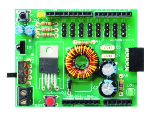
It helps at lower currents.  In the limited testing I've done on 2amp currents, it's not enough.  If you have a variable load that spans a wide range of currents, I'm I'm not sure there will be a "happy medium" that covers all the cases, and therein lay a potential problem.  Offhand, the only dependable solution I can think of  is to do the final voltage conversion/regulation on an attached shield/plate/cape.  Example:
 
Robot-Shield-4.jpg
 
By the way, I tried using a SEPIC voltage converter to bring the voltage back up to the nominal range, which is  2amps at 5 volts in the limit case that  I'm testing.  It would have worked except that for the SEPIC it to deliver that it needed to pull even more than 2 amps from the original 5 volt USB power source.  Because 2amps was already a high number, the SEPIC ended up needing more current than the USB power source could deliver, and so the USB power source shut itself down.  Obvious in retrospect.
 
Luckiily none of the boards I'm using presently have a need for  2 amps of current.
 
Reading through the USB 3.1 spec, it details the power budget and voltage loss that can occur due to cables, connectors, etc. It states that a USB powered device must able to operate with an input voltage of as little as 4.0V, which allows for the variations in the power supply output as well as the cable and connector losses. 
 
If a device requires more than 4.0V to operate, then it is not a properly designed USB powered device.  I don't know whether a RPi meets this spec of not.
 
The USB spec also specifies wire gauges to be used in cables for power and ground.  I know there are a lot of cheap cables out there that don't meet the spec.
 
RAL said:
I know there are a lot of cheap cables out there that don't meet the spec.
Yes.  
 
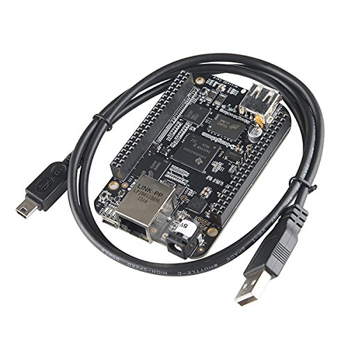
A large percentage don't even state which standard they comply with (1.x, 2.x,  3.x, or none of the above) on their jacket.  Even if they did, who knows whether the info is trustworthy?  It's become a real problem now that most SBC manufacturers just assume you have a proper USB power source and cable "lying around" to power their device.  Maybe that's why on Rev. C of the Beaglebone Black, they've changed to including an official micro-usb cable with the board.
 
510JaP3nFUL.jpg

 
It's dawning on me that I  should find a decent usb tester to sort through the motley collection of cables I've accumulated over the years so I can throw out the ones that are no good.  Anyone have suggestions on what test setup to use?
 
Supposedly the pi requires a minimum of 4.75V at the test points on the board
 
I found these power supply charts quite interesting:
 
http://www.cpmspectrepi.webspace.virginmedia.com/raspberry_pi/MoinMoinExport/OtherTestedPSUs.html
 
I wish they tested up to 2 amps, but the charts do illustrate the problems, as well as differences  among the different power supplies.
 
Anyhow, I'm going to switch my test case from 2 amps to 1 amp, because 2 amps through the USB port without a major drop in voltage doesn't seem likely to happen without jumping through hoops.  
 
Back
Top