DC power UPS?

Interesting!
 
What do you guys think about "long life" VRLA batteries?  "Long Life" might mean a "design life" of 8, 10, 12, 15, or 20 years, and they're intended to mostly just float.  I first ran across them while looking at the power sonic website today.  Prior to that, I hadn't realized there even existed "long life" SLA batteries.
 
The prices don't seem unreasonable for the 8 and 10 year ones:
 
http://search.atbatt.com/search?p=Q&lbc=atbatt&uid=469695848&ts=custom&w=%22long%20life%22&isort=price&method=and&view=grid&stateid=s6C26A26A2tFoYiXOv&cnt=45
 
A good fit for, say, an alarm panel?  Actually, the power sonic ones are big and might not fit in an alarm panel box and/or might be too heavy.  Not sure.  They do give a lot of Ah's as compensation though.  The lesser 7Ah CSB one would easily fit, but I don't know whether CSB is a trustworthy brand or not....
 
Even if you assume a service life of 70-80% of their design life, it seems like their annual cost would be on par with the per annum costs of regular general purpose SLA batteries of similar capacity--maybe even cheaper.
 
What's not to like?
 
Over the last couple of years here have gone to using POE / managable switches as many of the little network toys utilize 5-12VDC.
 
WIth these though use POE power splitters and initially started with Tycon midstream managed POE switch and Tycon POE splitters.
 
The managed midstream POE injector can be powered via 120VAC or 48VDC.
 
NeverDie said:
Interesting!
 
What do you guys think about "long life" VRLA batteries?  "Long Life" might mean a "design life" of 8, 10, 12, 15, or 20 years, and they're intended to mostly just float.
... 
 
but I don't know whether CSB is a trustworthy brand or not....
 
I've seen the long life SLA batteries, but haven't given them a try.  Guess I just wasn't sure if they really lived up to the claims of longer life.  If anyone has some actual experience with them, it would be nice to hear about.
 
I've had some normal-life CSB batteries in various UPSes.   They seemed ok.  No better or worse than other batteries I've owned.
 
That's good info.  Thanks!
 
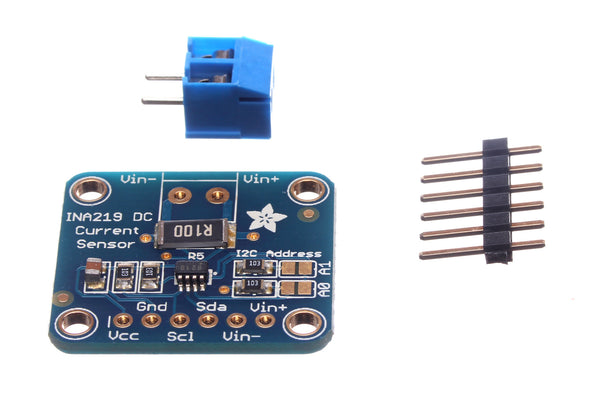
BTW, if anyone is motivated to make their own monitor or control circuit using a pi or something, I've tested the $9.95 INA219B breakout board (below) for simultaneously measuring voltage and current, and I found it in generally good agreement with measurements also taken by a Fluke 87V :
 
ADAF-14-CS_02_grande.jpeg

 
http://www.adafruit.com/products/904
 
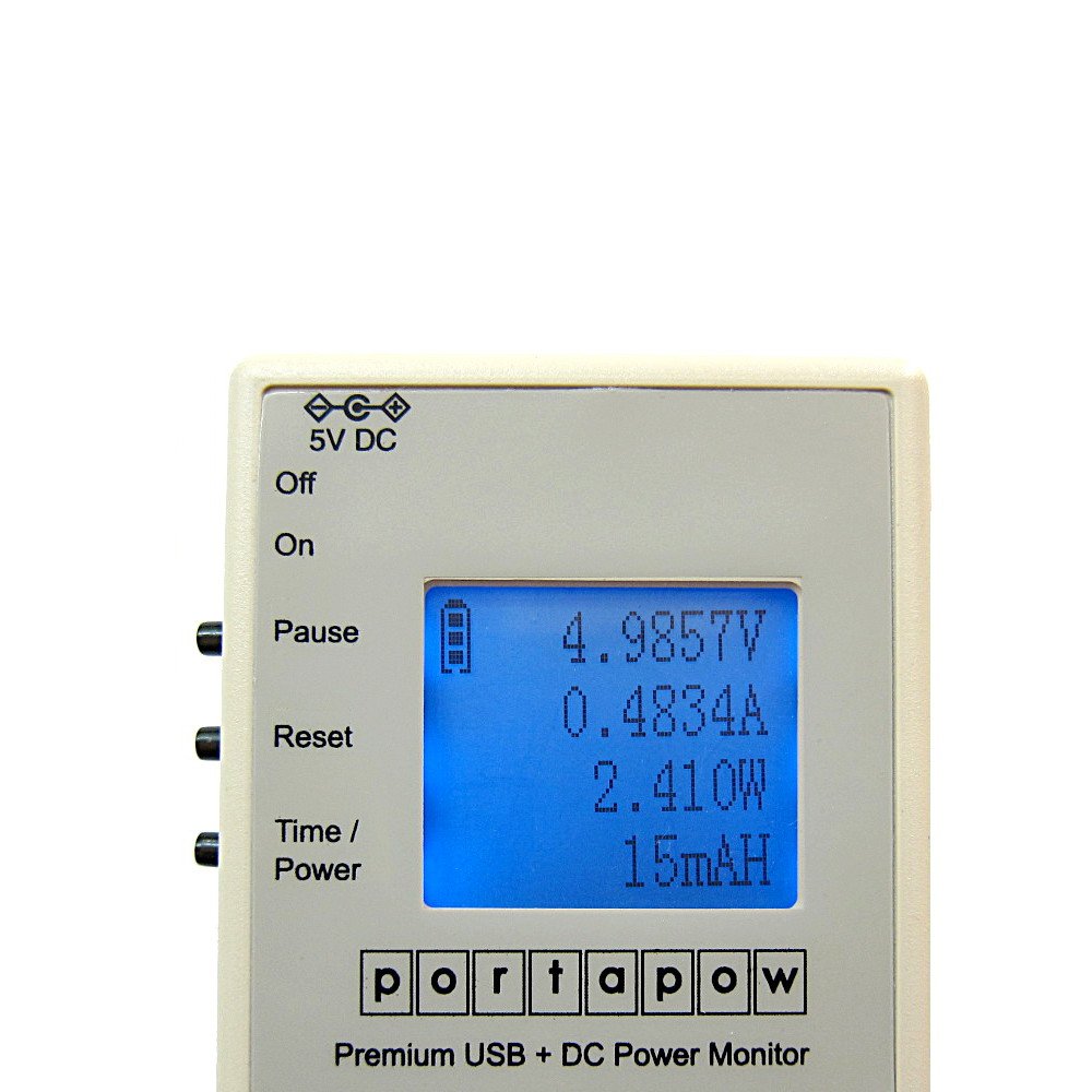
For instance, I found it to be more accurate than a Version 2 PortaPow, which costs 5x as much and which, because of its comparative inaccuracy, I ended up returning:
61Fl9pyitLL._SL1500_.jpg

 
http://www.amazon.com/gp/product/B00LZ07BG0/ref=oh_aui_detailpage_o04_s00?ie=UTF8&psc=1
 
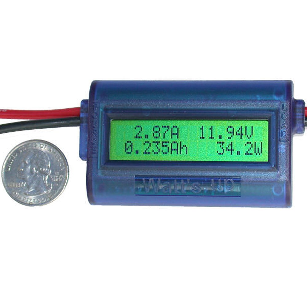
I was surprised I had to do that, as mjlorton had done what seemed like a reasonable youtube review of it that ended in praise for the portapow's accuracy, especially as compared to the even more expensive and more popular "Watt's up" RC power meter:
 
61QFn1sPEjL._SL1500_.jpg

http://www.amazon.com/Watts-Meter-Analyzer-WU100-Version/dp/B001B6N2WK/ref=sr_1_6?s=electronics&ie=UTF8&qid=1413212258&sr=1-6&keywords=rc+power
 
Anyhow, since you read the INA219B with a mirocontroller, you can have the microcontroller actually *do* something based on the info (like automatically terminate a discharge test when voltage declines to 10.5V), unlike the two power meters, which can't even log the datastream and can at best merely display their measurements (they have no interface to a microcontroller).
 
There have been several really good posts in this thread. 
 
I'm a big proponent of green and sustainable design.   When I do a build or buy analysis, I try and figure out the fun factor, any inovative elements which should be tried, and the impact of the project on sustainability.
 
So, a few aspects in my UPS thoughts.   We have failrly reliable power in my city.   So, most ot the time this UPS will be running on the AC/DC power supply.   I want efficiency there, because it will affect my ongoing monthly power bill.   And a part of the win will be the elimination of 4 to 6 wall warts into a single supply.   I will be powering network, security and automation components, not sensors, so each device will need more than just a few hundred milliamps.
 
The battery technology and cost is important, and, as was pointed out, there are some new SLA designs which might be long lasting and cost effective (VRLA).   I ordered a LiFePO4 battery and I'm hopeful my battery will last a long long time, so the truth will be in the pudding, as they say.
 
The battery montoring circuit portion of the UPS controller is an often overlooked aspect.   Most UPS designs, I've read, just trickle charge the battery, without active management.   The UPS portion of those supplies just follow the battery float.  So, even under power, the output of many off-the-shelf UPSs will not be fixed and regulated.
 
I chose a UPS controller with a microprocessor for managing the battery chemistry charging profile and a DC/DC converter.   The DC/DC converter allows the system to output 12v, regulated, not just float at the battery voltage.   The vendor also provides code updates.  
 
"RAL" pointed to the Altronix Al600ULPD8 as an off the shelf workhorse, and he's spot on for a robust design which has been on the market for a while.   
 
The ELKP624 is another example of a workhorse system, it takes the 16.5vac secondary off a transformer, rectifies, filters, and then trickle charges a battery   The circuit then feeds the regulator va a simple diode stearing circuit.  Which  is followed by a regulator for the chosen voltage.   But, when the battery drops below the regulator's input threshold, no regulation.
 
The items and techniques discussed by NeverDie would monitor the workhorse processes, but not manage them.
 
A smarter design, I think, is to put a DC/DC converter after the charging/stearing circuit.   This allows the system to continue to supply regulated power until the battery charge is depleted (if the battery technology can survive full depletion).    A microprocessor manager can taylor the charging process to the chemisty of the battery.   And follow the depletion curve so the DC/DC convertion is halted if the battery tech warrents it.
 
Another thought, and maybe some folks here have a notion of the comparison.   PTC vs fuse.    The PTC tech is nice because it self-resets, but at the cost of a quarter-volt or so of drop in the operating current range. 
 
I plan on using fuses.   Most devices these days are very reliable and burnouts are rare.   Again, its the ongoing efficiency element for me.
 
Hubert
 
daurtanyn said:
It's still four times more than the SLA battery you suggested, but it should last 4 times longer AND it doesn't have issues with being fully discharged. 
 
All food for thought.
Hi Hubert,
 
If by "fully discharged" you mean discharged down to nothing, you may want to re-check that assumption.  IIRC, LiFePO4 cell's still have a cut-off voltage somewhere in the 2.5V - 3.0V range (the recommended minimum voltage seems to vary by manufacturer) that you aren't supposed to allow it to discharge below or else it will affect the cells longevity (the more often it happens, the greater the impact).  Of course, maybe there's been some innovation or new development I haven't heard about, and if so, I'd be interested to learn about it.  Regardless, by itself it needn't be a deal breaker, as It seems like every chemical battery has a recommended discharge cut-off.  Even NiCd's, at least according to the manufacturers, even though large numbers of people claim otherwise based on their anecdotal experiences.
 
As to 4x longer, that might by itself justify the purchase.  What exactly is the claimed longevity for the battery you're considering?
 
All for one, and one for all!
 
You raise some interesting points.  Not sure I agree with all of them, though.
 
Just to set the record straight, the Altronix power supplies, such as the AL600, are microprocessor controlled.  They do more than just trickle charge the batteries.
And the output is regulated and filtered while running on AC. 
 
When the AC power fails and it switches over to batteries, the output voltage will drop as the battery voltage drops.  But I don't see much value in having a DC-DC converter to boost the battery voltage back up and keep it at exactly 12V.   The DC-DC converter will cost you some efficiency - figure 5 to 10%.  I'd hate to throw that away when I'm running on batteries.
 
Unless you need to power some devices that can't deal with anything other than steady 12V power, you're wasting energy.   Most of the devices you mention, like security, automation and network equipment are fine with voltages that are near 12V.  Many will re-regulate the delivered supply voltage internally down to whatever the chips inside need.  Usually 5V, 3.3V (and sometimes even lower). 
 
If you look at the discharge curves for SLA and LiFePO4 batteries, you'll see that as they reach their cutoff voltages, there is very little charge left.  The output voltage falls off a cliff, and at best, you would get a couple of extra minutes if you discharged it to 0V.   So, again, it makes little sense to me to use a DC-DC converter to try and boost this quickly dropping voltage back up to 12V for that small gain in run time.  You probably would do better without the converter and gaining back the run time that having it in there would cost you.
 
I understand that experimenting with stuff like this is fun.  If that's what you want to do, no problem.
 
Here I was thinking of purchasing the Raspberry Pi DC UPS to play with but not to use; well at least for the time being. 
 
I did buy an RTC clock for mine and I have already trashed out the SD card probably from just pulling the plug on it.  (so I really should buy the backup power for it).
 
I do utilize the car stuff as I always want to make sure that the car starts after shutdown of the carpc and its very low on the WAF sometimes if the car doesn't start. (my fault type of stuff).
 
Having a picopsu with a 12volt charging circuit battery does work on my home automation software computer; but its a bit of a PITA for one computer / software. 
 
That and I do have a sub panel on the HAI Leviton Ominipro II with its own battery.  It does have battery status wires going to the main panel et al stuff.
 
And all of my lighting is mostly 120VAC so it will not turn on my lights should the power failure occur at night.  I do get mesmerized watching graphs of this and that; almost hypnotic like.
 
Same goes for my Leviton HAI OmniPro II.  The lighting scheduling stays but the lights do not go on if there is a power failure.
 
Hello NeverDie,
 
The DC/DC converter in the OpenUPS I've chosen (from mini-box) is a buck/boost converter and it will shut down when the input voltage drops below 6V.   The operating range is from 6V to 30V.   The threshold where it shuts off is configurable.   For a SLA I would probably set it to 10v.
 
If I didn't have an exisiting 12V AC/DC / 6amp power supply, I would probably have gone with a 24v input/battery configuration.   As is, I'll bump my 12 supply up to it's maximum voltage output.
 
Mini-box sells good stuff.  I have used their wares (well for automobiles for years).  For a time there were a few counterfeiters selling stuff like theirs on Ebay.
 
Bill started the original post and wondering if he got his answer(s)?  Or too much information?  Or gave up?
 
pete_c said:
...I have already trashed out the SD card probably from just pulling the plug on it.  (so I really should buy the backup power for it).
It seems to be a known design flaw that has adversely affected a lot of people.  I got my first pi about a week ago (the model B+), and I was very surprised to learn that a known fatal flaw like that remained unaddressed even in the most recent update release (the B+).
 
Anyhow, in-line with the current discussion on this thread, maybe a small SLA battery on a trickle charger actually makes sense in this scenario?  I haven't done any searching to find what's best, but I did notice that this vendor (whom may well be a shark for all I know, as I don't know them from Adam) has some inexpensive 6 volt SLA's, and some of them cost $3-5, and some of those weigh as little as 0.66 pounds:
 
http://www.batterysharks.com/Emergency-Lighting-Batteries-s/1660.htm
 
Perhaps someone here knows of even better/smaller options/lighter options?  To do the bare minimum, all it need do is supply power for the short time it takes the pi shuts down, and so a cheapskate solution might even forego a low-voltage cut-out circuit (as discussed above for a more proper solution), especially since the batteries are cheap to begin with.  Anyhow, I've only barely started to think about it, but clearly something is needed to avoid the problem you encountered.  I guess the only reason to consider SLA in this instance is that the circuitry would be very simple, thereby keeping costs low on what's supposed to be a cheap SBC.
 
Thinking about RAL's comments, I'll have to agree with his critiques.   It probably isn't necessary to have a DC/DC converter downstream of the input/battery elements.  
 
Adding a picoUPS and an SLA battery would work for my use case; powering network, security and automation major components.  Each component (modem, router, switch, Elk gateway and ISY) is very likely to have its own local internal regulation down to a working voltage.  
 
The PicoUPS, also by mini-box, can charge a SLA battery, and cut-over to the battery when the AC/DC supply goes out.   Pete mentioned using mini-box stuff for car projects (the PicoUPS 100 version is general purpose and the PicoUPS 120 is optimized for car applications).  So, if you have the AC/DC supply, it's a nice option.
 
If starting from scratch, the Altronix Al600ULPD8 or similar unit is probably the right solution for a DC Power UPS in this use case.
 
Yeah here an only related to my Leviton Omni-Pro II panel I have a sub panel with it's own power supply and batterie(s). 
 
This device has a 120VAC PS attached to the board (as the main panel does) with two SLA battery terminals.
 
It has one zone connection back to the main panel and only related to the battery backup.  The subpanel footprint is the same size as the main panel.
 
The above is for function relating to security / automation panel.  While playing a bit; it's not touched and it just works 24/7 just fine.  (life and safety stuff).  The only playing right now is relating to the installation of a microrouter with network, serial and 3G/4G failover to see if it works.  Tiny device powered by the panel itself.  (power draw is higher with modem running).
 
Relating to small network connected trinkets using POE splitters if they are away from the main configuration (basement).  I use these also for POE attached IP cameras and touchscreens (all network cabled).
 
Long term playing and testing in production of my irrigation software running on an Arm based Pogo Plug (Seagate Dockstar) trashed the USB sticks (well one of two) after about a year of running 24/7 and doing a nightly backup.  Changed over to using a USB connected SSD drive.  No issues to date and its been over one year running this way.  Power to the device is via a POE splitter (as earlier mentioned).
 
First Rasberry Pi running 24/7 OS / Automation software running 24/6 trashed 16Gb SD card in about 6 months. No backup UPS was utilized.  First impressions are OK for playing but not really for long term stuff.  Here just added an RTC clock.  I would like to change the base OS.  I can though try just a boot on the SD to a USB connected SSD card.  It should work and there it will not maybe trash out the MMC card.
 
Testing an Intel atom based touchscreen with 1Gb MMC.  Switched the device over to using a PATA port SSD while its still utilizes the flash for an EFI boot.  This device is on 24/7 and also POE powered.  I have already seen though a constant on / off using the MMC flash can and will trash soldered on MMC.  The device was meant to be on 24/7; it has no off switch or a battery backed up CMOS (EFI or coreboot).  That said it does run wintel, linux or android based OS's. 
 
Local neighbor here switched over to LED lighting with solar panels.  He buried two 12VDC car batteries in an irrigation box outside and has the charging controller in a PVC box outside with a little plastic window on it.  No timers are set and it looks to be that the LED lighting runs all night.  Looks that he is using some sort of light / dark switch for the lighting.  Here also converted to LV LCD lighting and currently just utilizing 12VDC DIN power supplies.  Its been over a year now and running fine.  Ideally though would like to do the solar panel / outdoor battery stuff and some means to automate LV separating lighting zones.  I have seen now LED LV "coach" style lamps that run on 12VDC and look very similar to my current 120VAC lighting.  Changing over all exterior lighting to LV would be a nice thing.  (batteries / solar panel would be the icing on the cake).
 
I did a rough tally, and It turned out the cost saving from piecing together an SLA UPS for a pi from scratch didn't seem justify the hassle, or the delay.  So, on a hunch, this afternoon I ordered a USB Lipo "power bank" to investigate whether it might serve the purpose.  Admittedly, the one I picked is more expensive and has more capacity than what is needed, but in relation to this thread that doesn't really matter.
 
518jahmByWL._SL1500_.jpg

http://www.amazon.com/Vinsic-20000mAh-External-Battery-Tablets/dp/B00NGG9IDU/ref=sr_1_12?ie=UTF8&qid=1413323422&sr=8-12&keywords=vinsic+power+bank
 
As a first step, I'm hoping that if I don't power-on the pi until after the power bank batteries are already fully charged, the pi will draw all it's power from the input power to the power bank and the pi will, at least initially, only draw power from the power bank batteries if there's a power failure.  i.e. I'm hoping the power bank will, in effect, function as a DC UPS without the hassle of explicitly wiring one up. After a power failure is over, my hunch is that the pi will continue to draw whatever power it needs, and that the new load of recharging the batteries won't interfere with that.  However, since I don't actually know that it will happen that way, I plan to test out that hunch empirically using a dummy load.  If it works, then I'll put the pi in harms way and try it again.  If the pi then gets through it unscathed, I'm going to take it as the solution and move on.
 
However, as I'm writing this, it occurs to me that by setting it up like this, the ongoing current drawn by the pi may (?)  thwart the LiPo charge termination algorithm, possibly causing the LiPo's to be continually charged, even if there never is a power outage.  I'm not sure what to think about that.  Is it a valid concern?  If it were to happen, what might be the consequences?  Bottom line: is it a fatal flaw?
 
Now that I think about it, I think the scenario that will likely happen isn't that.   Rather, when I first turn on the pi, the pi probably won't draw from the input power at all because the charge cycle will already have terminated.  Instead, the Pi will draw down the batteries until some sort of  "recharge" threshhold is reached.  Then the pi actually will draw from the input power, and the batteries will be gradually recharged from the difference in the input and output power, minus inefficiencies.  Eventually the batteries will be recharged enough that the charge termination algorithm will kick in and the charging will stop.  And that cycle will repeat over and over for as long as the pi is turned on.  I don't know what the depth of discharge is likely to be, but I'm guessing that if that's how it pans out, the recharge cycling won't be good for the LiPo's, and they'll prematurely wear out.  In that case, doing it this way is the wrong approach.
 
Shucks.  Neither of those scenarios sounds good. 
 
Well, one thing I did notice last night when I was looking into pulling together an SLA UPS from scratch is that there are already a ton of used Belkin 12 volt gateway UPS's for sale on Ebay.  I could easily get one for around $20 or less, slide in a new 7Ah SLA battery (I've checked, and the replacement batteries are easy to find for about $12), and bang, I'd have a 12 volt DC 36 watt UPS.  In my case, I could buck convert the 12 volts down to 5 volts, and presto, I'd have a Raspberry Pi UPS.  It would be a kludge, but if I can fit the buck converter inside the UPS enclosure, it might be a tidy kludge, and either way it could be put together without much effort for less than $40, including shipping costs.  In fact, for the raspberry pi, I think I will will ago ahead and do that, just so I can cover the risk and be done with it..  For slightly more cost , I might even be able to use the 8 year "long life" SLA battery I mentioned above in this thread.  I'd need to confirm its dimensions would fit the case of the Belkin Gateway UPS, but it turns out that the long life SLA battery manufacturer is the same one that manufactured the ordinary 7Ah SLA battery that Belkin used in the gateway UPS originally.  Perhaps at the end of the day this will turn out to be the path of least resistance for some other lightweight devices also....
 
After sleeping on it, I think the power bank will probably work just fine as a short-term test-bed for a beaglebone or a pi or a random SBC.  It should have enough capacity that it shouldn't recharge-cycle very quickly, if in fact that's what it does when configured as above.  I'll measure out exactly what it does do and what kind of UPS-like characteristics it might or might not have after it arrives.  If nothing else, it should have enough capacity that it can also be used as a convenient 5 volt usb power source in short-term portable applications.  
 
For something that's more 24/7, like datalogging sensors, it looks like a pre-owned gateway UPS (above) will, after modding, be an easy and cheap solution, and so I ordered one of those also.  In the case of the raspberry pi, it turns out it may be a feature rather than just a hassle to buck convert the UPS's 12 volts down to the 5 volts that the micro usb connects into the raspberry pi, because if needed I can tweak the the buck converters final output  voltage to compensate for any voltage drops the micro usb cable itself might introduce,  Last night I was reading that micro usb cables and/or an inadequate power supply are the two most commonly encountered sources of instability and SD corruption in pi's,  Luckily, I haven't encountered any of that yet, and I hopefully never will if all goes well in setting up the powerbank and UPS,  [As an aside: moving the pi's root directory off the SD card also seems commonly recommended as further bulletproofing to avoid the SD card getting distructed from too many writes, especially to the log files.].
 
If there's interest I'll post how it went.  Otherwise, I just wanted to give my thanks again to all who contributed to this thread.  Over and out.
 
Back
Top