Help, can't find my IR receiver window!

I updated the links, sorry about that.

I have a 15 ohm resistor since I bought the 500 1/4W assortment pack, so I should be good to go.

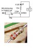
<newbie>The transistor has 3 pins: collector, base, and emitter. Which pin connects to what?

Also, can I leave this project downstairs in my basement, and run 2 wires to upstairs where the LED is, or does it have to be close to the LED?</newbie>

The package shows that "Ic" is 200mA, is that the minimum required mA the VDC powersupply has to support? Last but not least, the package says Vebo = 6V, do I still have the right part (since you mention a 12VDC power supply)? Thanks
 
The transistor pinout should be shown on the back of the package from Radio Shack, but it is very likely like this: if you lay the transistor down in front of you with the pins pointing downwards and the flat side facing you, the left pin is the Emitter, center the Base and right pin the Collector.

Don't worry about the specs you saw like Vebo, these are maximum pin to pin voltages that the device can withstand. Vebo would be a maximum emitter to base voltage, we're not exceeding more then 2 or 3 volts with a current limiting resistor (the 2.2k part).

The IR LED is actually being driven at very high peak currents (close to 1 amp) for very short pulse durations. This is ok because the pulses are so short that it cannot heat up the LED or the transistor to any degree. Handheld remotes work the same way too.
 
The package does show the pin layout, I just don't know which pin goes to what part of the circuit ;) How can I get 1amp out of an IR LED if my power supply is only a few 100mA ?
 
[hand hold] ;)

In the circuit diagram, the emitter is at the bottom (the one with the arrow), the base goes to the 2.2 resistor, and the collector goes to the 15 ohm and IR LED part of the circuit.

[/hand hold] :D

Enen the most ordinary DC wall wart has a filter capacitor that can provide a large current for a very short time, measured in microseconds. If the wall wart is only 200 mA or so, it might be a good idea to add an extra filter capacitor across it for more current capacity. If you can get a can-type capacitor rated for 220 or 470uF (or more) at 25 Volts then add that across the +12v supply for extra oomph.
 
I am sure I can find a wall wart with more mA, just wondering what the minimum requirements are without having to get more parts or making things more complicated. Thanks for the help!
 
Many times you can actually bounce the IR signal off the ceiling or wall if they are a light color.

John
 
Well I tried getting this to work, but no luck. This is the result :

http://www.mydotsoft.com/products/my.Gallery/?album=IR

I know it looks bad, but that's all I had to work with ;)

The 2 black cables go to the mini plug which plugs in to the Ocelot
The stereo wiring goes to the female mini jack which is where I plugin my LED using a male mini jack I put together

I found a universal powersupply, set to 12VDC, providing around 300mA, but I don't think it's regulated. When I measure the 2 contact terminals connected to the speaker wiring (IR LED), it measures 9.33VDC all the time, and around 9.60-9.80VDC when the Ocelot transmits an IR command.

Is it possible at all to tell from the picture if I did something wrong or should I just get a breadboard and redo it?
 
I built one of these a while back (thanks Guy) , but only use it occasionally. What I ended up doing is putting the whole thing in a 2x3 project box along with a 9v battery so that I wouldn't have to run a pair of power wires to it. I don't use it that much, but it still has the original battery in it. I don't know how long the battery would last with average use, but it did make for a fairy simple install. Just an idea....
 
I want to keep the circuit in a box downstairs, and run the LED to my wall upstairs using just 2 wires (either alarm wiring, or a cat5), so I don't have to run power. That is if I ever get this working lol. Do you have any pictures of yours?
 
I'll try to get ya a couple of shots of it tomorrow... it's downstairs stuck to the wall.
 
I'm trying to get a good look at the transistor from the pictures (and yes, this is a rather "rough" setup!) and I think you have the emitter and collector reversed. Try inverting the two "end" terminals on your transistor. The base is in the center and looks correct.

The pulses are so short that you'll never be able to see them with any accuracy with just a voltmeter. You would need a scope to do that. One thing you might try is adding a visible LED to the output side to see any activity. To do that, add a visible LED and a 1k resistor in "parallel" like this:

+12v---------IR LED-----15 ohm R------------->to transistor collector

+12v------Visible LED----470 ohm R----------->to transistor collector
 
Gemini: Thanks, pictures always help!

Guy,

I found an online manual for this transistor, which also contains the pinout information:

http://www.chipcatalog.com/Philips/Datasheet/36375.htm

Do you still think I have it wrong? I will switch it tomorrow (and maybe try to get a small breadboard). Thanks Guy!

PS: Wouldn't I be able to detect the IR using my Digital Camera, or is it too fast for that as well?
 
Isn't the resistor to the base wrong? He wants a 2.2K according to the schematic shown below which I believe is RED RED RED Gold. I think he has a 2.2 ohm resistor instead (and if you look in Guy's "hand hold" post above, he indeed said "2.2 resistor" but I think meant "2.2K resistor").

Resistor Color Code Utility

Might be my eyes though as I had a tough day at work and its late here.

As far as the transistor, look HERE on page two (TO-92 type case).
 

Attachments

  • irblaster2.jpg
    irblaster2.jpg
    13.6 KB · Views: 39
I meant to grab a 2.2k, I will have to check that, but hopefully that's the problem, thanks!
 
Back
Top