You are using an out of date browser. It may not display this or other websites correctly.
You should upgrade or use an alternative browser.
You should upgrade or use an alternative browser.
Help, can't find my IR receiver window!
- Thread starter electron
- Start date
")
Guy Lavoie
Active Member
red-red-red is indeed 2.2k, so there is no problem there. The fourth gold band indicates that it is a 5% precision part.
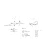
The Philips datasheet linked above shows the bottom of the transistor, which is confusing since you're normally looking at the top of the part. The angle of your pictures don't make it 100% clear but it looks like it is reversed. Once again: if you lie the transistor on its back on the table in front of you with the pins pointing downwards and the flat side (where the part number is written) facing you, the emitter is on the left, the base in the middle, and the collector on the right.
Here is a pictoral diagram of what it should look like:
Attachments
You know, you might have figured out the problem, I saw the diagram on back of the box, but I never realized if this was the bottom or top. The pictoral diagram shows exactly what I did, but the transistor could be reversed just as you mentioned, I will check it out tonight.
One other thing I noticed is that when I set my universal power supply to 12VDC, it puts out around 16VDC (probably becaues it isn't a regulated power supply?), does this drop to 12VDC when in use, or is this going to be a problem? Thanks!
Rupp: The powermids do sound much easier, but there are 2 reasons why I don't want to go that route: 1) My RS 15-2117 remote has a similer repeater system (RF->IR), and I have some serious noise problems, and 2) I love doing things myself, just more rewarding (as long as I don't burn the house down that is). I have learnt a lot about electronics in the last few months just by playing with resistors and having you guys help me out with my projects, and it is getting addicting.
Guy Lavoie
Active Member
The 16 volts doesn't matter, most inexpensive wall warts put out a somewhat higher voltage without a full load. If you're worried about burning out the IR LED, you could always replace the 15 ohm resistor with a 22 ohm but I wouldn't worry about it.
I agree with you Electron, learning to make your own little circuits is quite rewarding and addicting. Plus, you can make things in ways that are not commercially available, such as hide the IR LED in a picture frame, molding, etc and put the rest of the circuit elsewhere. I have at least as much fun designing and building things as I do using them afterwards.
I agree with you Electron, learning to make your own little circuits is quite rewarding and addicting. Plus, you can make things in ways that are not commercially available, such as hide the IR LED in a picture frame, molding, etc and put the rest of the circuit elsewhere. I have at least as much fun designing and building things as I do using them afterwards.
I too find it's often more fun designing and building than using.Guy Lavoie said:I have at least as much fun designing and building things as I do using them afterwards.
Guy Lavoie
Active Member
I used a free program called "Paint". It normally comes with every Windows version I've ever seen. Just click on "Start" --> "Programs" --> "Accessories" --> "Paint".
I also use Paint for quick sketches. Unlike Guy's, however, mine look like they were done in Paint.electron said:You drew all those parts with just paint? Impressive!
You can also download the free schematic editor from www.expresspcb.com. It's pretty straightforward. It's designed to work with their PCB layout program and board manufacturing service but it works fine standalone.
Rupp
Senior Member
I like doing my own projects as well but by the time I'm done with them they look like a bowl of spaghetti and function about as well. :lol:
I actually built one of these about a year ago but no matter what I did I couldn't get the device to work from about 4 feet and further.
I actually built one of these about a year ago but no matter what I did I couldn't get the device to work from about 4 feet and further.
Guy Lavoie
Active Member
Well Rupp, if you ever want to take another shot at it, just ask questions here...
Guy Lavoie
Active Member
If you did use a 2.2 ohm resistor, then you might have blown the transistor, so if it still doesn't work even after replacing the resistor and switching the transistor leads, try another transistor.
http://www.mydotsoft.com/products/my.Gallery/?album=IR2
I just tried it, and no go. I don't have any other transistors, and I am not sure if RS has any left, they are out of stock a lot when it comes to electronics. Is there anyway I can test the one I have now?
I just tried it, and no go. I don't have any other transistors, and I am not sure if RS has any left, they are out of stock a lot when it comes to electronics. Is there anyway I can test the one I have now?
Similar threads
- Replies
- 0
- Views
- 1K