I2C 16bit ADC expansion for WC8

WC32 already supports USB flash key storage device.  You can read and write flash storage in PLC directly on WC32.  Using external EEPROM on WC8 can store some values, but not as easy as WC32 to store on USB flash key.
 
As far as CPU and memory goes, they are used almost 100% all the time, if the CPU is not used, it will loop to next task and keep itself busy all the time. WC32 has a lot more RAM unused. WC8 uses almost all the memory already.
 
Cool.  I saw the usb port in the picture but seemed to have missed the part about how it was being used.  I don't think I will be storing data on that one.

Oh dear, here comes the arbitration...
 
klaatu said:
So far eight RAMs has been more than enough, and I haven't touched the VARs.
 
 
In VERY early versions of the code, RAM and VAR were only 16 bit variables. That's been increased to 32, which combined with AND/OR/MUL/DIV/ADD/SUB operations let you store multiple things in a single RAM or VAR  by clever use of bit positions.
 
In the latest few versions of the firmware, we have a far easier way (using unions) to conveniently address "parts of" RAM values.
 
As a whole 32-bit word:
RAM1 (32 bits)
 
As two 16-bit words:
RAM1H (top 16 bits of RAM1)
RAM1L (bottom 16 bits of RAM1)
 
As four 8-bit words:
RAM10 (top 8 bits of RAM1)
RAM11 (bits 16-23 of RAM1)
RAM12 (bits 8-15 of RAM1)
RAM14 (bottom 8 bits of RAM1)
 
and as 32 individual bits:
RAM1B1 (bit 0 of RAM1)
RAM1B2 (bit 1 of RAM1)
....
RAM1B32 (bit 31 of RAM1)
 
The same for RAM2, RAM3 through to RAM8.
 
If you're familiar with structures and unions in C, think of these as UNIONS - the same physical memory is referenced, just in different ways.
So if you were to set RAM1 to 0
then set RAM1B3 = 1, RAM1 will now be 4  (because the 2^2 bit has been set)
 
It does, however, make more complex programs FAR easier to write, read and maintain.
(Especially so if you use my web-interface utility that lets you use symbolic names for things!)
 
Thank you for that Ross.  I've been using the 8 bit rams, I think from the example codes, and that has seemed like I have plenty of locations for my use so far.

Looking now in my 18a guide I see it has the 1-bits, I hadn't noticed that, probably because the examples I initially used hadn't demonstrated employing them.  I threw it together fairly rapidly, and other than a few initial weirdnesses with my DS18B20 daisy chain method, which were due to my hardware and not the wc8, it has just worked, and I moved on to other things and happily forgot nearly everything about it.

My manual says 'This only available for RAM1'.  Having even 32 1-bit places to store booleans suddenly makes it seem like it has scads of ram.  I'm re-writing my code...
 
rossw said:
(Especially so if you use my web-interface utility that lets you use symbolic names for things!)
!
something else that has escaped my vision.  my internal filter was set pretty hard on firmwares.  where please?  searching for 'utility' by rossw only produces this post.
 
klaatu said:
My manual says 'This only available for RAM1'.  Having even 32 1-bit places to store booleans suddenly makes it seem like it has scads of ram.  I'm re-writing my code...
 
Sorry, my bad. Yes, the single-bits are only on RAM1 for some reason.
 
 
klaatu said:
something else that has escaped my vision.  my internal filter was set pretty hard on firmwares.  where please?  searching for 'utility' by rossw only produces this post.
 
Sending you a PM about it.
 
Yes, the single-bits are only on RAM1 for some reason.

The way this was implemented would take too many opcodes to address everybody's two bits worth. :)
 
If this would have been implemented say... like this... with the variable (RAM1) and bit as a parameter (RAM2=0-31)
 
   CLR RAM2
LOOP:
   BNE RAM1B   RAM2
   GOSUB BITSET
   INC RAM2
   TSTLT RAM2 32
   GOTO LOOP
   ....
 
Loops could be created to test and send sequences using an indexed addressing scheme instead of 32 discrete tests.
 
Larry,
 
You could do shift to the left then OR the bit in or XOR a bit out to manipulate on other RAMs, or directly OR and XOR the 2^x bit position.
RAM1 has 32 bit separated operands that can be addressed individually is for easier to understand for people want using bitwise operator.
We did not give every bit of RAM bitwise access is to reduce the operand table size. 8x32 takes up a lot of operands that most people have no need for.
 
You are absolutely correct, there are many ways to handle the data bits. Sharing different ways to handle data bits will help more people understand how to write PLC code.
Thanks.
 
Well then how about
 
TSTN RAM1B  63
 
to test the  MSbit bit in the RAM2 and access any of them with only one more opcode? A single, full option  opcode, with an indexing parameter, makes coding much simpler to use than an opcode to every single style of operation.
 
 
OTOH: Motorola CPUs used this style over Intel. Motorola processors used about 60 opcodes compared to Intel's thousands of opcodes with independent labels that were much more limited. Unfortunately despite Motorolas 2 MHz CPUs running circles around Intel's 33MHz CPUs Motorola lost the popularity fight and died when Apple dropped them for their products.
 
Most vehicles and controllers used Motorola CPUs years ago. Code was much simpler and had more powerful options.
 
Getting the itch for another WC8/32 project... maybe to develop a hydronic heat pump control mixing panel with outdoor reset. Maybe start with just temp  monitoring and simulation first.
 
All the best!
 
Larry this is interesting you mention this, I was thinking of stuffing the 32 bit VARs with two 16 bit sensor values each, which I can later decode/separate after bringing it out of my db. haven't yet thought about the plc for that, I have still only used very little of the syntax. perhaps another way I might get data from four of these ADCs w/o using external ram or eeprom.

Most people may not have any need for them, but I think the 32 single bits are great, I used mostly booleans for my purpose, and did it all using only about 10 bits of RAM1, after seeing Ross mention it. Some of the guide examples show storing booleans directly in the 32 bit RAMs, when I first saw that I thought it was just due to early development or device limitations. But then I saw the 16 and 8 bit values, and used them. Somehow I missed the 1 bits, didn't read down far enough

I am going to try using eeprom to hold the counter value thru reboots, resetting the combined value in the db after serial outages is one more detail can that bear simple automation

Just checking in, saw Support had posted and needed to see if parts were in play & being tested. my ADCs are still somewhere in the mail, and we just had more storm floods and power outages, be back in few days...
 
klaatu said:
I am going to try using eeprom to hold the counter value thru reboots, resetting the combined value in the db after serial outages is one more detail can that bear simple automation
 
 
I have a number of applications with counters - one of the longest-standing ones of course being rainfall.
My "solution" to the volatile counter problem is to keep the "real" counter on a server that has decent non-volatile storage.
While the volatile counter value is "not less than the last time", I use an incremental value of (last_count - current_count) added to last_known value.
If current_count is < last_count, it means that either the counter has reset, or overflowed, in which case I just use last_known + current_count.
It isn't perfect, because there's a small but finite time where the counter COULD have incremented, but then overflowed or reset, but not been captured.
The reality is that it hasn't been an issue in 20 years, so I don't even think about it any more. (Caveat: as long as you are sampling fairly frequently - in the case of Rainfall, even every 5 minutes is probably good enough)
 
Hi Ross, thanks.  yes, that's essentially what I would like to do with the eeprom.  I'm already storing the count on a server, but I would rather have it preserved in the wc8 itself, and not have to do the update in the db.  I don't mind that a count or two might be missed during bootup, I realize that may happen.  1 watt hour lost among thousands isn't going to be a big deal

the wc32 and most of the sundry parts are here, I was planning on doing this ADC exercise first in this board and leaving the wc8 to its working self for the moment.  once I have the ADCs on a little board with cabling and working PLC, I can move it to the wc8 with the least interruption, hopefully.
 
however, I am not getting a high confidence level on the wc32 power input.  the manual says it is a switcher good to 25v for my board version 7, and I bought a box of 12v supplies because I needed a few for some other equipment, and I also bought a 12v relay board.  but now that the wc32 is here, I don't see the components I would expect for a switching power reg, and the terminals on the pcb are clearly marked +9v.  It looks pretty similar to the 2.2.2 wc8 in that corner of the board, not at all like the 2.3.8 board where the regulator is obviously different.  not powering it on until I know what's up, if it is really 9v w/ no switcher then I need to send it back

so I put an ADS1115 on a little protoboard and wired it up to the running wc8.  so far, my attempts to acquire data, based on the plc that I am making from what I read in the datasheet, and the userguide plc i2c example, is returning FF for both bytes coming back from the read.  I have one analog input wired to a voltage divider, around 1.5v, and another input wired to ground, they both read as max values. so now waiting on some known working plc example
 
 
klaatu said:
however, I am not getting a high confidence level on the wc32 power input.  the manual says it is a switcher good to 25v for my board version 7, and I bought a box of 12v supplies because I needed a few for some other equipment, and I also bought a 12v relay board.  but now that the wc32 is here, I don't see the components I would expect for a switching power reg, and the terminals on the pcb are clearly marked +9v.  It looks pretty similar to the 2.2.2 wc8 in that corner of the board, not at all like the 2.3.8 board where the regulator is obviously different.  not powering it on until I know what's up, if it is really 9v w/ no switcher then I need to send it back
 
That doesn't sound right. Only the very first of the WC32 boards I got (still at prototype stage) had a linear regulator. Even the version BEFORE final release had switching supply. Can you take a picture of the board for us? Which way is the USB connector oriented? (facing up, or off the side of the board?)
There should be a board revision printed on the silkscreen in the corner by the ethernet connector, can you read that?
 
Edit: I took a picture of a Version 7.0 board for you (I think this is the currently shipping hardware)
WebControl32-ver7.0.jpg

 
And here's a closeup of the SMPS area (to the left of the power connector and up to the USB connector)
WebControl32-ver7.0-smps.jpg


I've looked on mine, and yes - does also say "9V", but it's perfectly happy with a lot more. Certainly 12-24V is no problem!
 
 
klaatu said:
so I put an ADS1115 on a little protoboard and wired it up to the running wc8.  so far, my attempts to acquire data, based on the plc that I am making from what I read in the datasheet, and the userguide plc i2c example, is returning FF for both bytes coming back from the read.  I have one analog input wired to a voltage divider, around 1.5v, and another input wired to ground, they both read as max values. so now waiting on some known working plc example
Sounds like you've got its address wrong. Returning all FF means it's not replying on the bus.
 
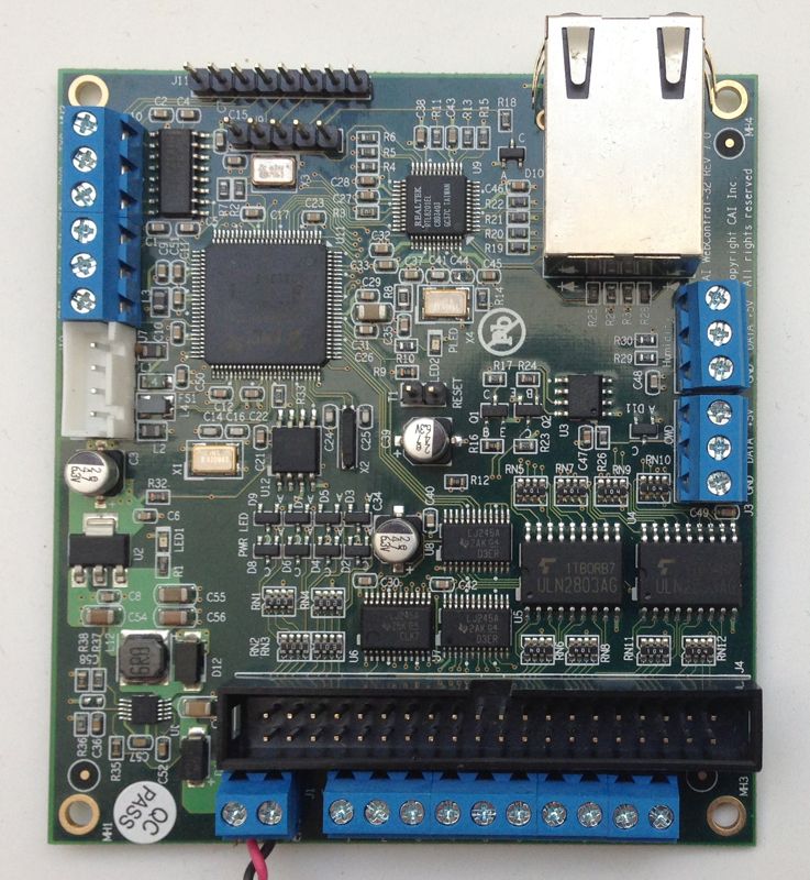
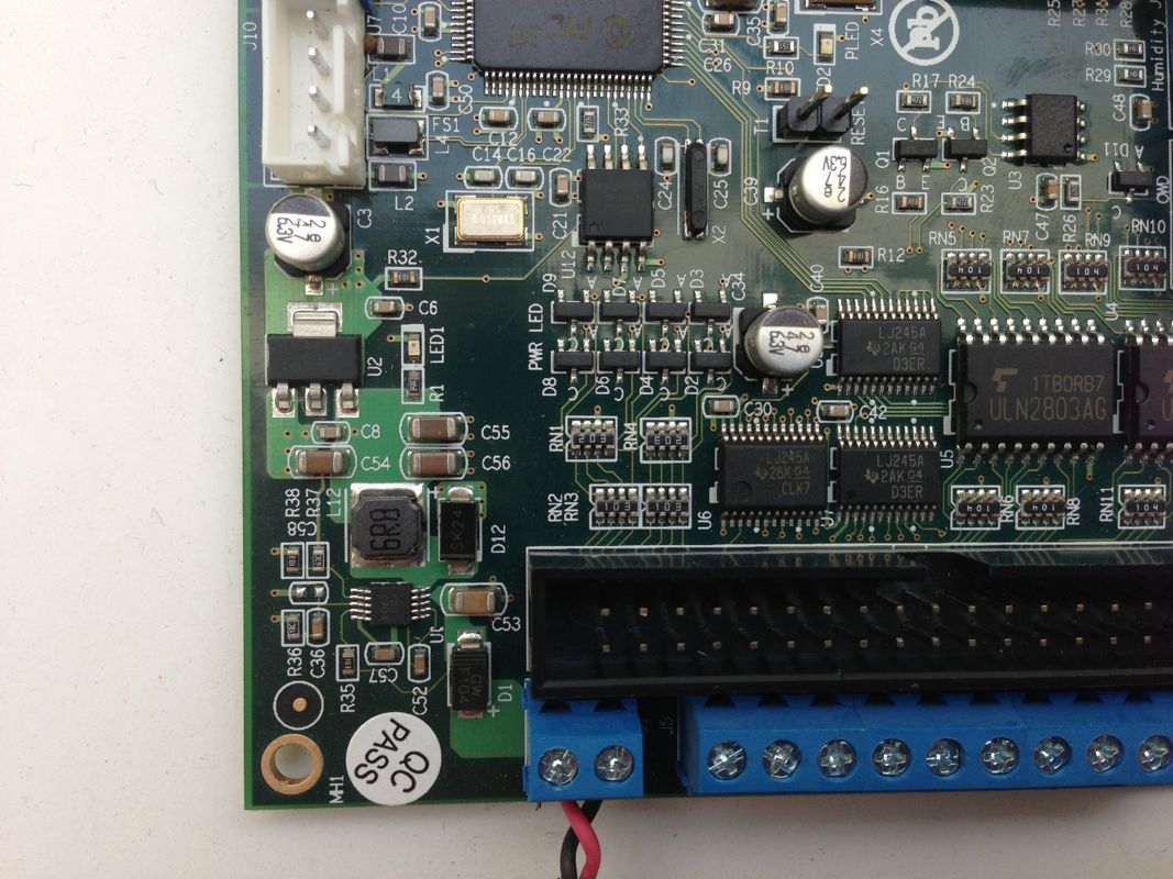
Yes it appears the same as your board. it seems the switcher is quite tiny.  And the vendor verified that despite the +9v labeling it is good to go for the full range.  thanks for the confirmation and the pictures
 
 
rossw said:
Sounds like you've got its address wrong. Returning all FF means it's not replying on the bus.
 
Yeah I had that thought, and even tried putting all four of them on the bus, each wired so that all four addresses were there, and tested each.  some simple code or byte logic thing that I haven't learned yet, or have forgotten thru disuse
 

As far as the address, both cai support and the datasheet say that grounding the addr pin will make it 0x48, and that's where I started.  hex 48 is 1001000, adding the low zer0 bit for the write makes it 10010000 = 0x90

    i2cwrite 1 0 0x90   # 10010000 address
    i2cwrite 0 0 0x1     # 00000001 pointer to config register

the first half of the first config byte sets the input, 100 for aip0 single ended, so 1100

the second half is the pga, I tried various values, but 000 for +/- 6.144v seemed like it should be fine for a max 5v input
the last bit is the continuous or single shot mode, I tried both.  single is a 1, so 0001

gluing those together makes 11000001 = 0xc1   for aip0, singleread, pga = +/- 6.144v.  so next line is

    i2cwrite 0 0 0xc1

selecting other pga or mode options might make this 0xc2, 0xc3, or 0xc4, etc
 
selecting one of the other inputs would make this variously 0xd1, 0xe1, or 0xf1, etc

 
the second config byte in their example, and the defaults, with comparator disabled, is 10000011  =   0x83

    i2cwrite 0 1 0x83

config set.   next set pointer to conversion register:

    i2cwrite 1 0 0x90    # address 0x48 plus write 0 bit appended
    i2cwrite 0 0 0x0      # points to Conversion register

next come the reads:

    i2cwrite 0 0 0x91        # address 0x48 plus read 1 bit appended
    i2cread 0 0 RAM21    # store MSB aip0 conversion value in MSB RAM2L
    i2cread 1 1 RAM20    # store LSB aip0 conversion value in LSB RAM2L
 
put it where it can be seen:

    SET VAR2 RAM2L     # 65535


the default data rate is 128 SPS, about 8ms, I don't know how the wc handles these timings. I tried some various delays for the read, based on the BMP180 example, but no help


Please follow the page 11 on the datasheet, on the right hand side was the example what to write to I2C bus.
We have not received ADC module yet, so that we can not write code to test.  Once we received it, we will write code to test and publish it here.
 
there are three portions of command sequences:
write to config register
write to pointer register
read conversion register
 
You are on the correct path to get this module to work :nutz:
 
Hi.  Yes, I wrote all that out to illustrate that I had done just that.  But the quickstart example in the datasheet uses differential input, and continuous conversion.  I have single ended input referenced to ground, & I don't know if continuous conversion works with the wc.  in the bmp180 example you used single read from what I can tell.  I tried both and still got FF

published tested code would be just fine, ty.  I knew you would buy economy, I paid for epacket to get a slight head start  :)
 
Back
Top